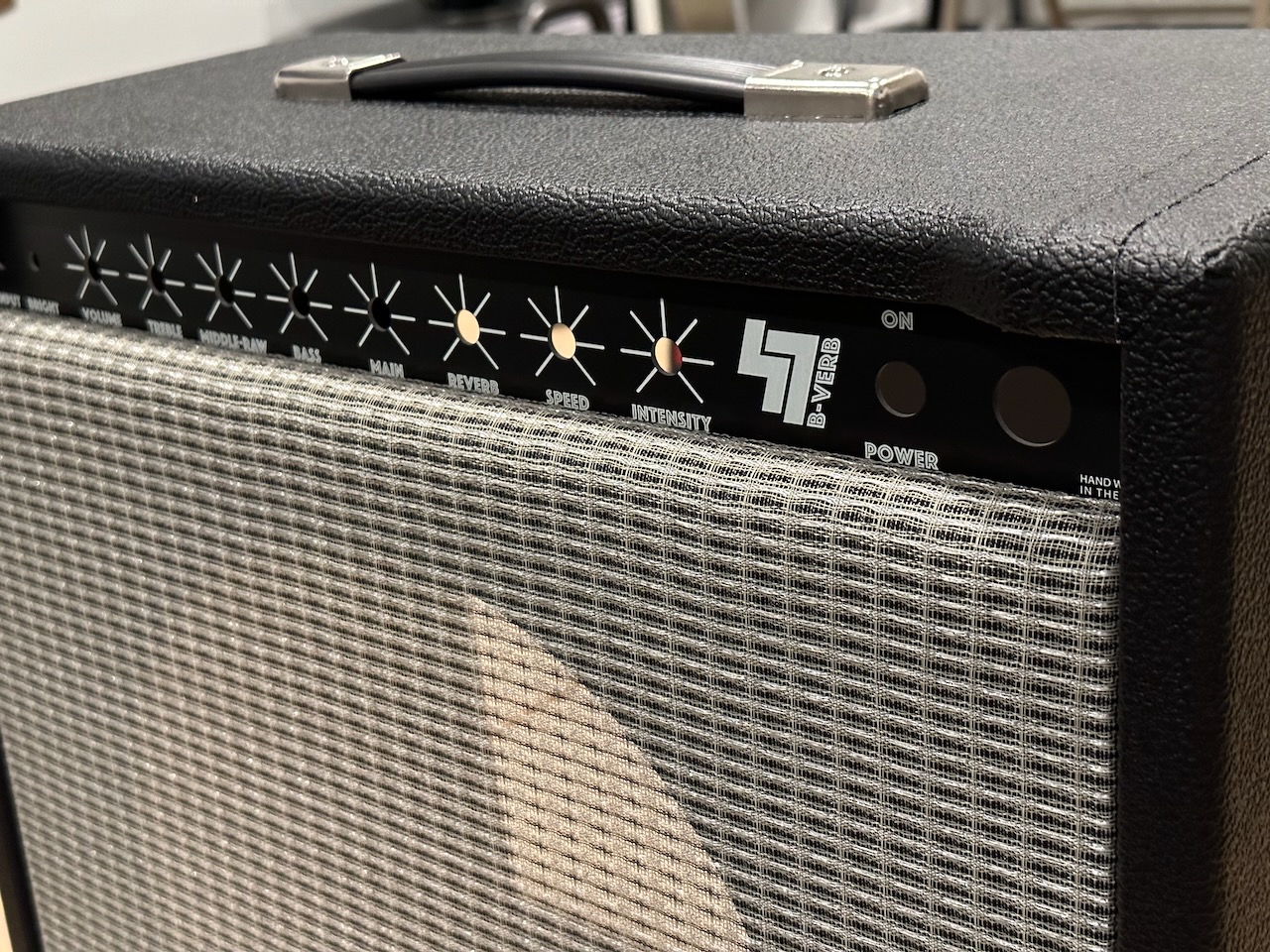
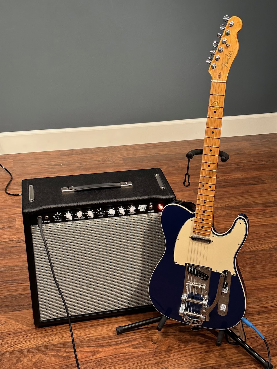
A one-channel Fender “Blackface” (AB763) amp with 6G16-style bias wiggle tremolo


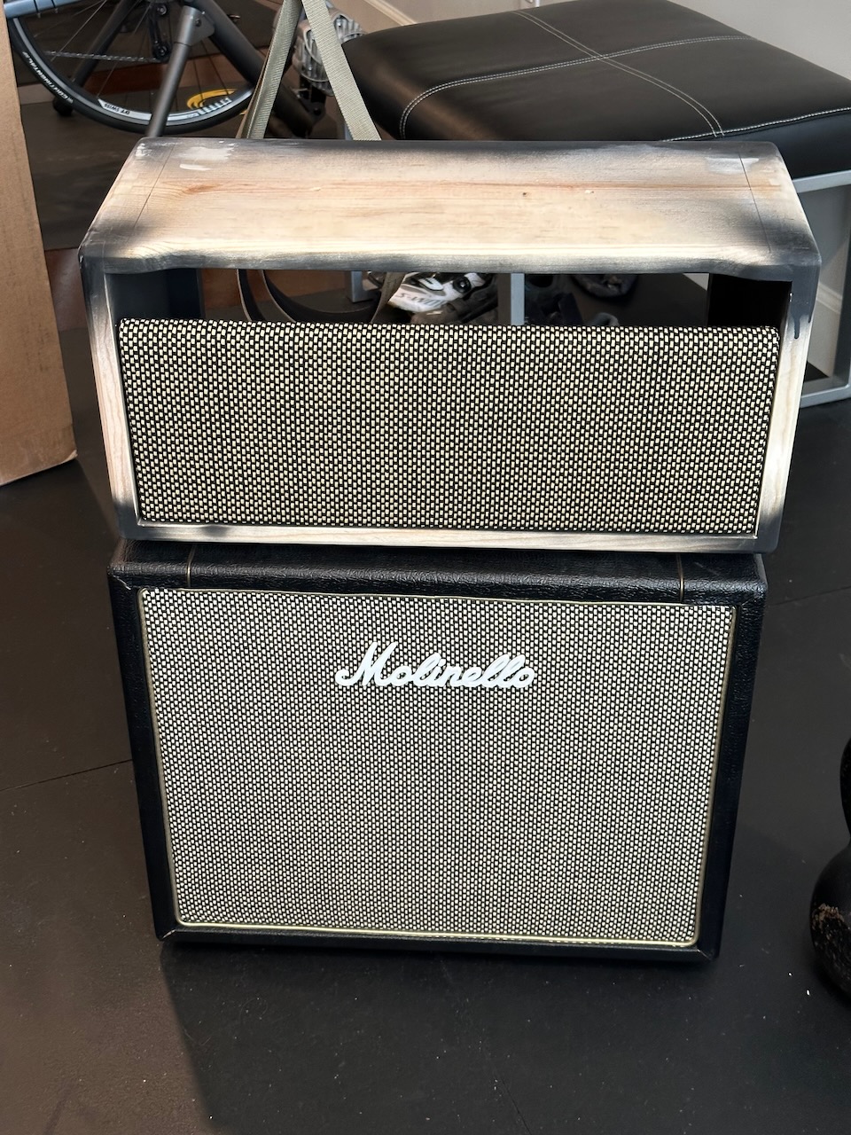
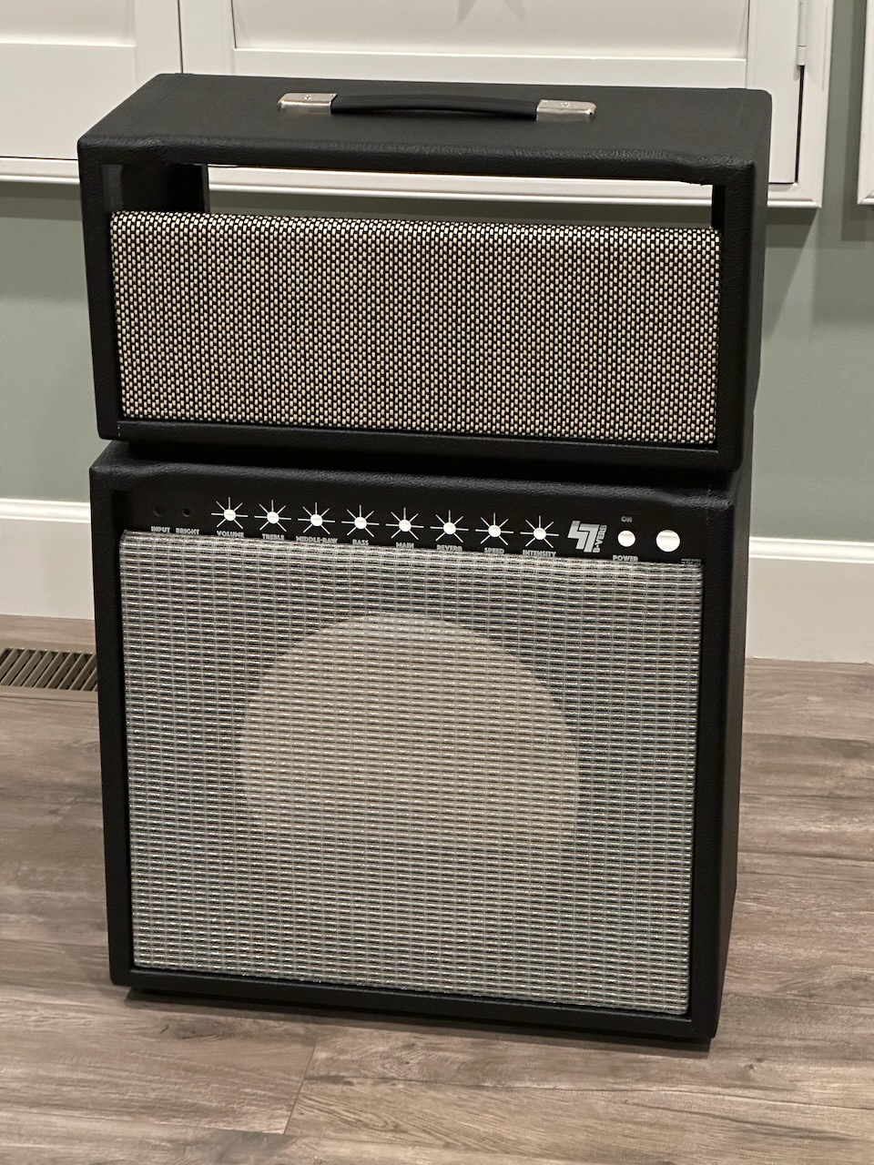
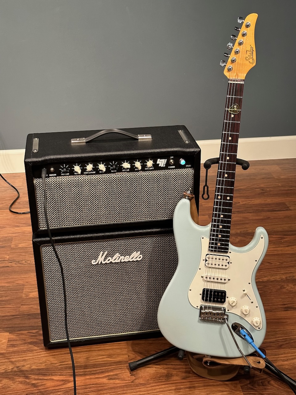
The same amp, but as an amp head


| Class | AB, All tube |
| Output | ~22 Watts |
| Circuit | Fender AB763 with 6G16-style bias tremolo |
| Bias | Fixed Biased, adjustable |
| Preamp Tubes | ECC83/12AX7 (3), ECC81/12AT7 (2) |
| Output Tube(s) | JJ 6V6S (2) |
| Rectifier Tube | GZ34 |
| Transformers | Power - 125P23B (MOJO761EX), Choke - 125C3A (MOJO778), Reverb Driver - 125A20B (MOJO776), Output - Musical Power Supplies OT20PP |
| Cabinet | Hand made by Boyd Timothy |
| Reverb Tank | Mojotone 4AB2C1B |
Dimensions
| Combo (Mk I) | Head (Mk II) | |
|---|---|---|
| Width | 19 7/8” | 19 7/8” |
| Height | 18” | 9 1/2” |
| Depth | 10” bottom, tapering to 9” @ top | 9” |
| Weight | 31 lbs. | 22 lbs |
Special Features
There are a few things I added to these amps that are a bit of a departure from a standard Fender AB763 circuit but I feel were worth it:
- Power switch on the front panel (a lot more convenient than reaching around to the back of the amp)
- No standby switch (these aren’t really needed)
- Master Volume Knob. This is a Type-2/Lar-Mar type which makes these amps so much more versatile.
- Bias Tremolo. Modeled after the Fender 6G16 circuit’s tremolo. I prefer the smoothness of this over the opto-coupler. Got the idea for this from Hoffman’s 1-channel AB763 project.
- Mid-Raw Switch (taken from robrobinette.com). Turn the knob all the way down and you have Deluxe Reverb (6.8K minimum) mid scoop. Turn it all the way up and you essentially cut the tone stack out entirely and it brings the amp into tweed-sounding territory.
- 3-way Bright Switch. There’s a little mini On-Off-On switch next to the input jack for controlling the bright cap values. Switched down gives a little brighter than normal sound (47pF). In the middle is off/bypassed. In the up position, it’s noticeably brighter (120pF cap).
- Reverb Dwell Control. On the back panel I’ve installed a 1M linear potentiometer to control the amount of signal that’s sent to the reverb tank. It’s just one more way of controlling the reverb sound and you can go from very subtle to very splashy.
- Switchable output impedance next to the speaker output jacks: 4/8/16 Ohms.
- Jack tips for measuring the bias. There’s one jack tip attached to the power tube screens. I also attached a jack tip to each power tube’s cathode with a 1 Ohm resistor between the jack tip and cathode pin. This makes it really easy to measure the plate current because 1 millivolt equals 1 milliamp.
These amps started out as a challenge to build a Fender “Blackface” reverb amp for under $500 – issued by my father-in-law. He’s an amazingly great guitar player and was looking for an amp he could use with his classic rock band. He ended up picking up a lightly-used BOSS Katana 50, and loves it.
I got into the hobby a few years late. I probably could have built one for under $500 before the prices of everything went up significantly during the pandemic. The big ticket items add up quickly: power transformer, output transformer, reverb tank, power tubes, and all the other tubes.
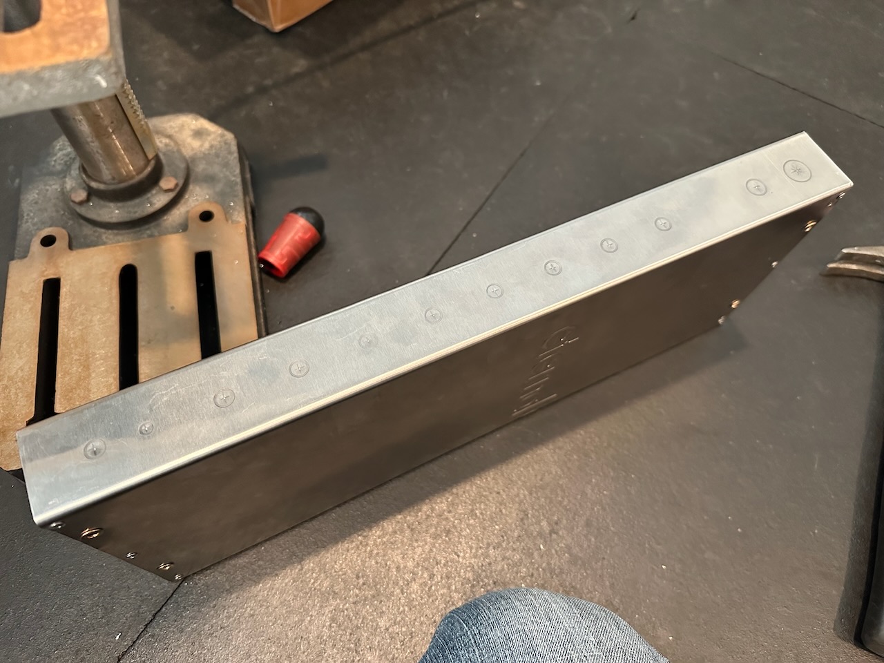
Still up for the challenge to see if I could still build one of these amp relatively inexpensively, I started by building a chassis out of the front panel of an old tankless water heater that’s been collecting dust in my garage.
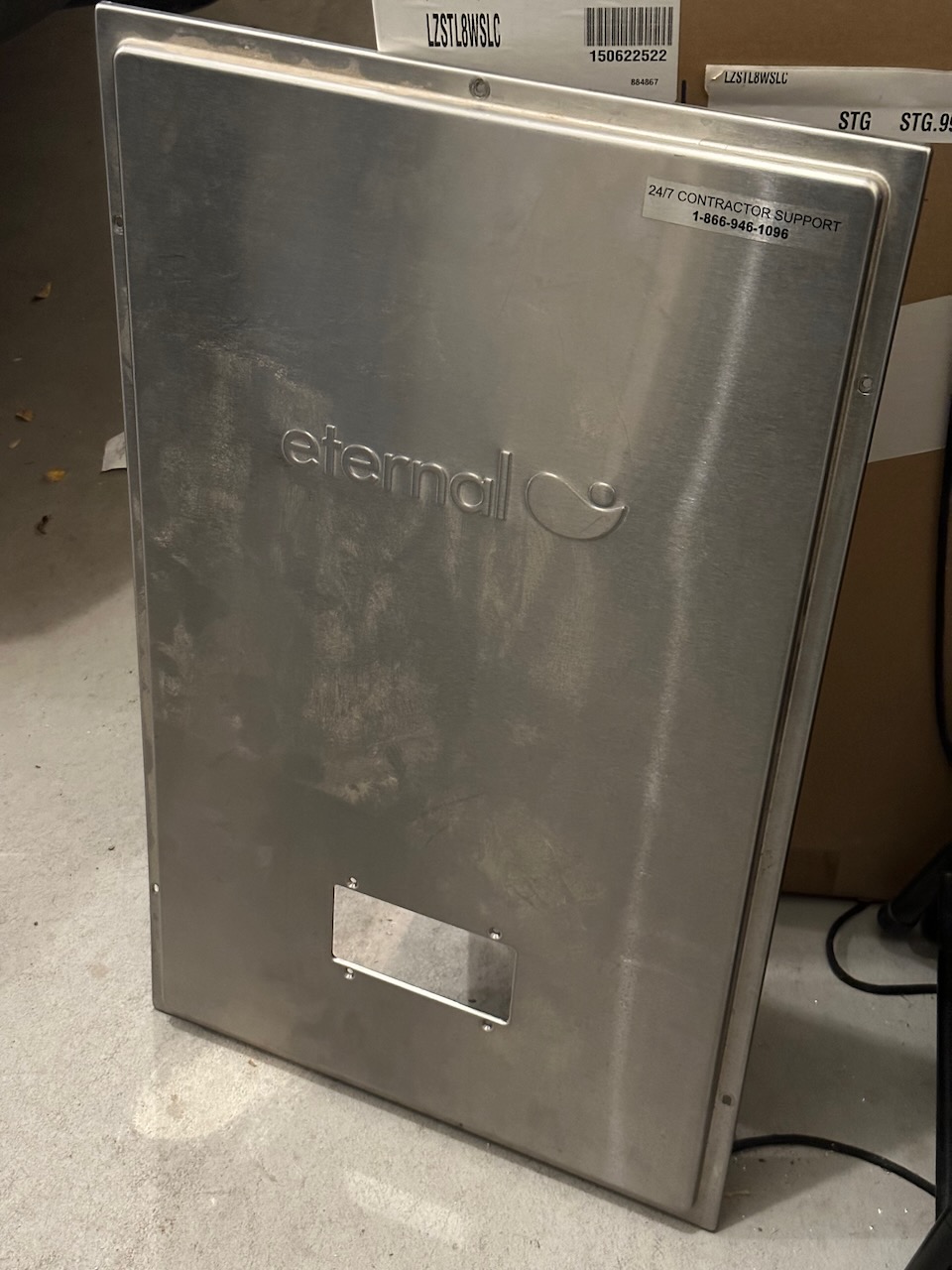
I grew up building duct work for my dad’s HVAC business and knew that I could probably bend a c-channel chassis and ends that I could pop rivet into place. During Thanksgiving afternoon my dad and I visited his shop and that’s exactly what we did. Note: I will never use a stainless steel chassis again – what a huge pain it was to cut holes into! But, it’s done now and has some sentimental value because my dad (in his 70s) contributed to it.
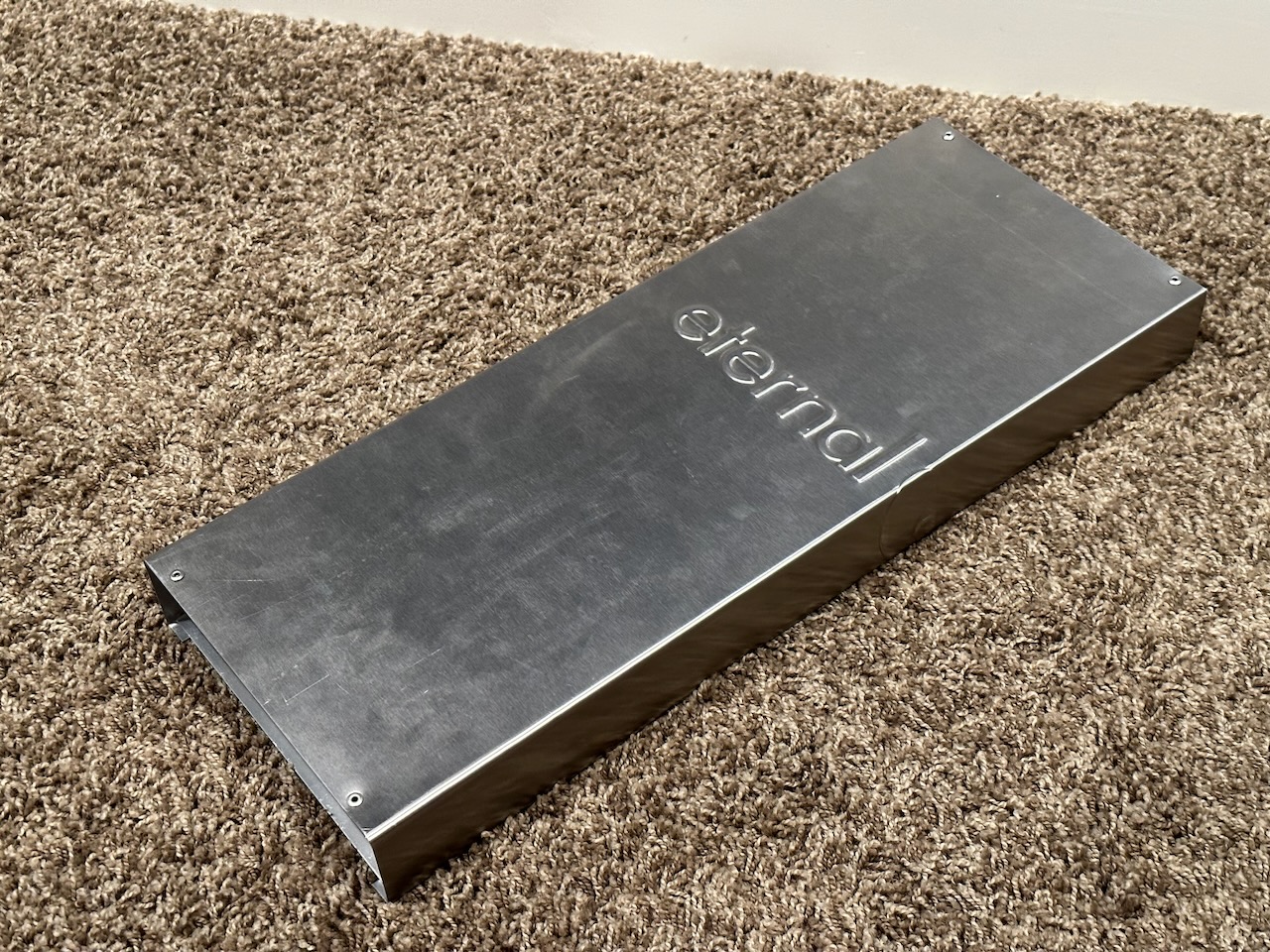
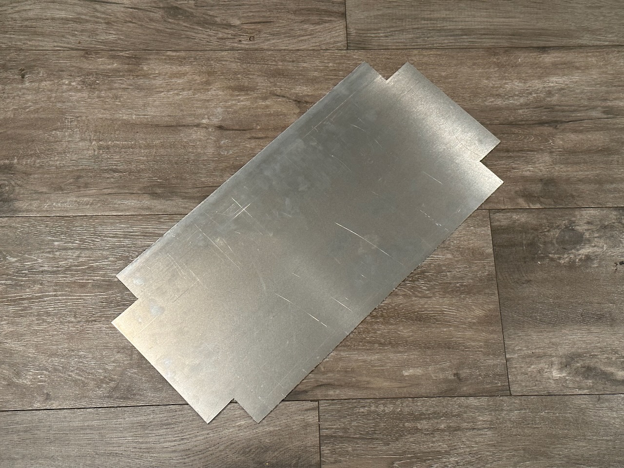
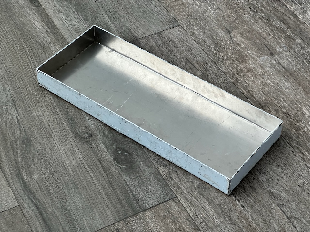
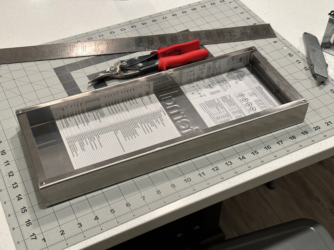
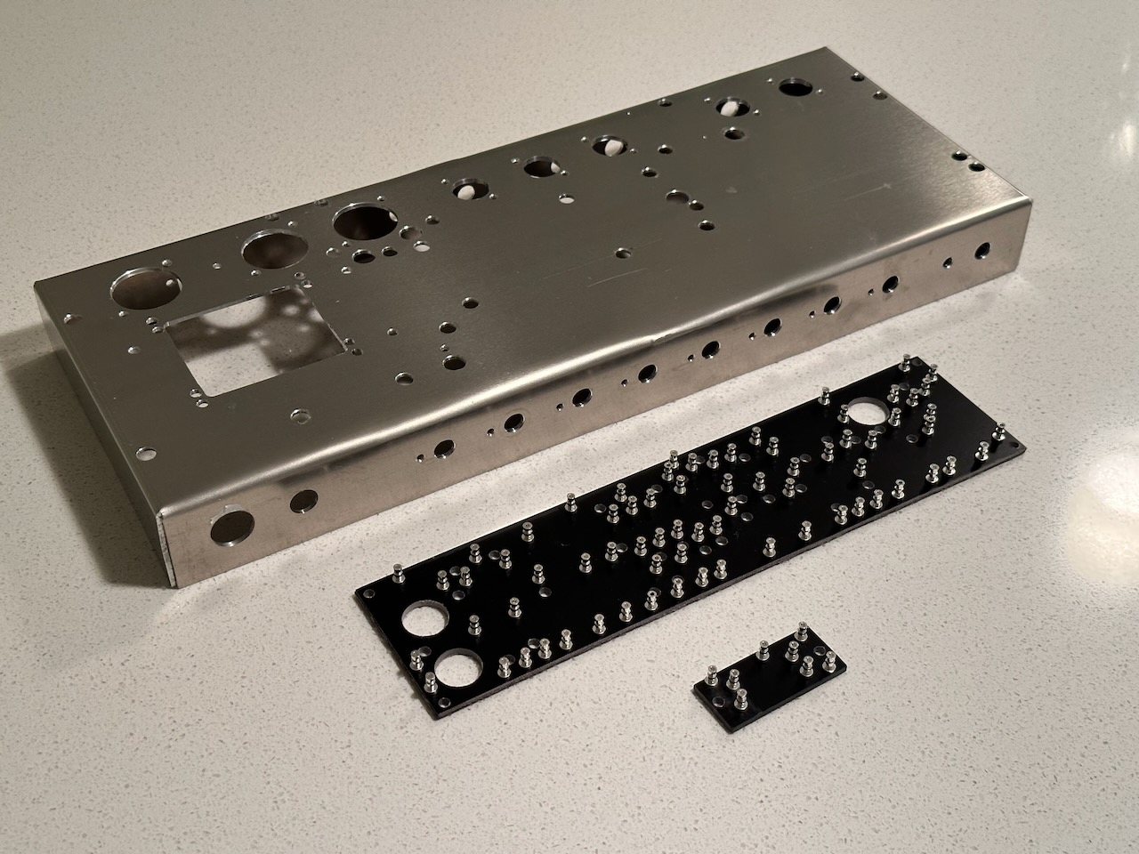
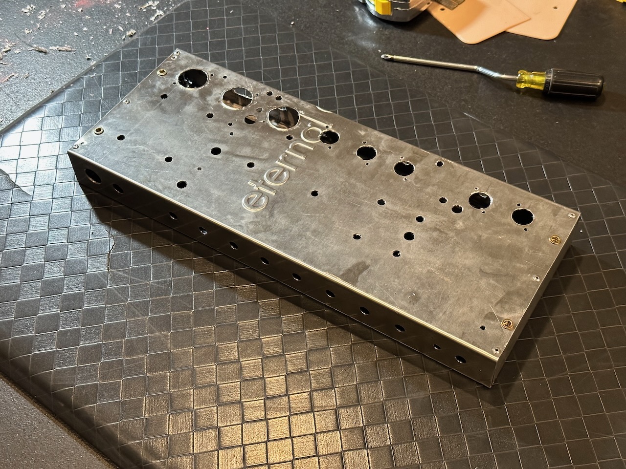
For the second version of this amp, dubbed the “Mk II” by my friend KingFan, I was smarter and bought a sheet of 5052 0.090” aluminum and used a box brake at a friend’s shop. It turned out MUCH better and was infinitely easier to work with:
I tried to do a lot of research ahead of time and found Rob Robinette’s Blackvibe 6V6 design which looked really cool. But, I wanted to have reverb and tremolo. That led me to discover Hoffman’s 1-channel AB763 schematic and layout. I still wanted to stay true to the original Fender layout as closely as I could in general and so I kind of morphed these two designs together.
I really liked the sound of the Deluxe Reverb but wasn’t really that big a fan of the size and weight. With that in mind, my goal was to build a single-channel Deluxe Reverb but about the width of a Princeton Reverb. To give a 12-inch speaker enough room, I made the height of the combo cab a couple of inches taller than a Princeton Reverb.
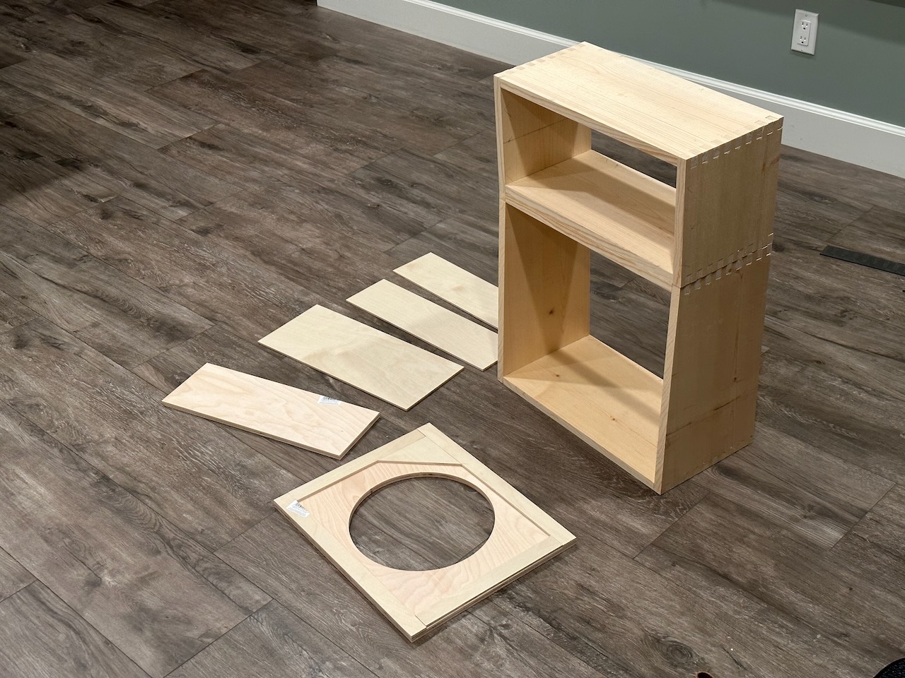
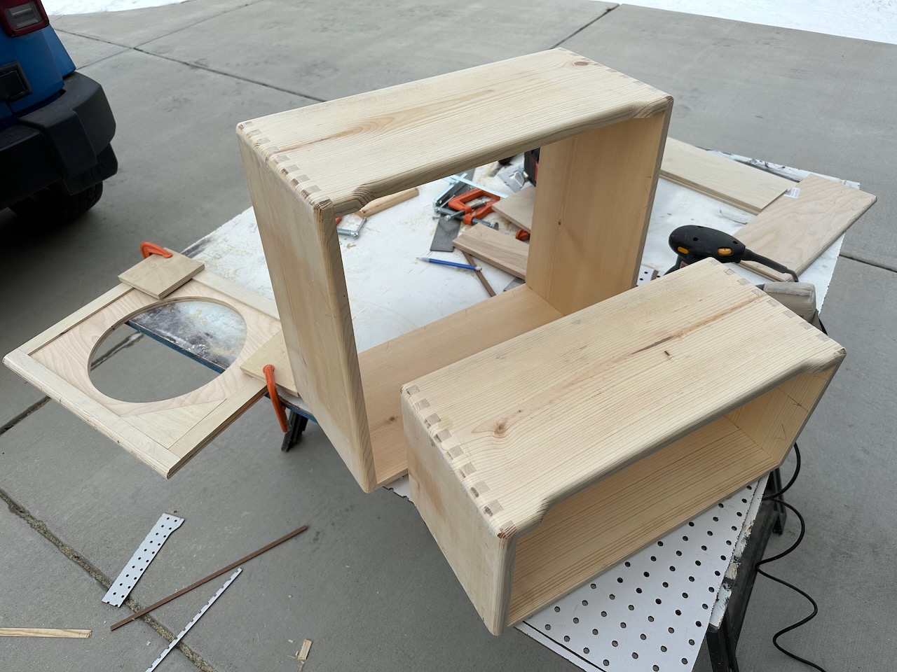
N+1 amps is always the right number of amps, of course, so while building the combo cab I decided to pre-build a head cab that would fit the same size of chassis. A lot of people don’t recommend buying lumber from Home Depot (or other big box stores) but I didn’t have the time to go during a work day up to a specialty lumber store. So, I spent a few minutes going through a LOT of pieces of boards looking for the straightest ones and with a few defects as possible.
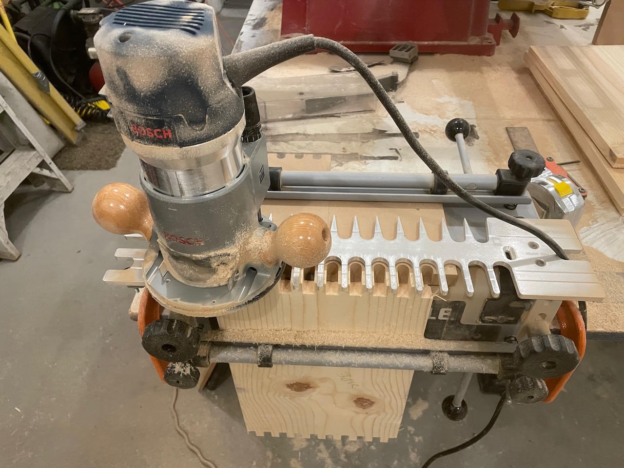
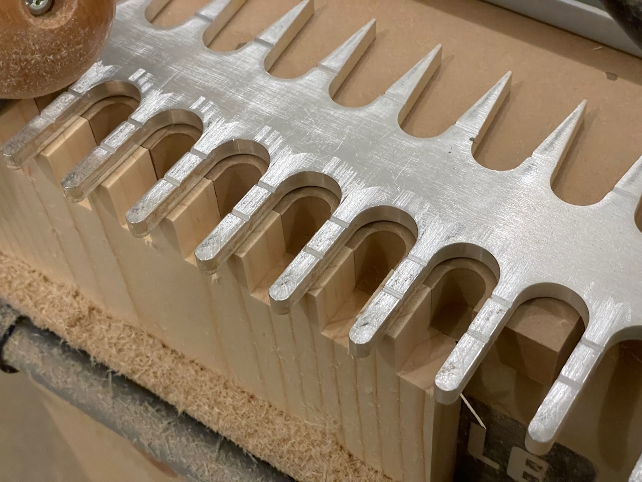
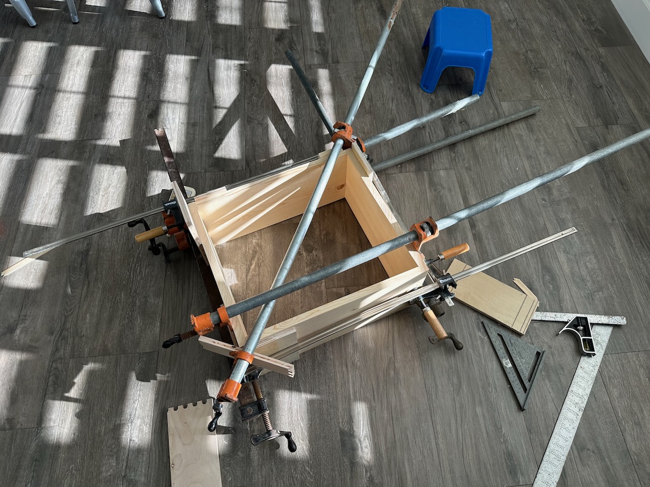
My good friend Erich let me borrow his fancy tool and router to make all the box joints. These cabs are definitely extremely solid. A couple of tips for “next time”…
- Don’t cut box joints inside of a garage!
- Don’t use fast-setting wood glue!
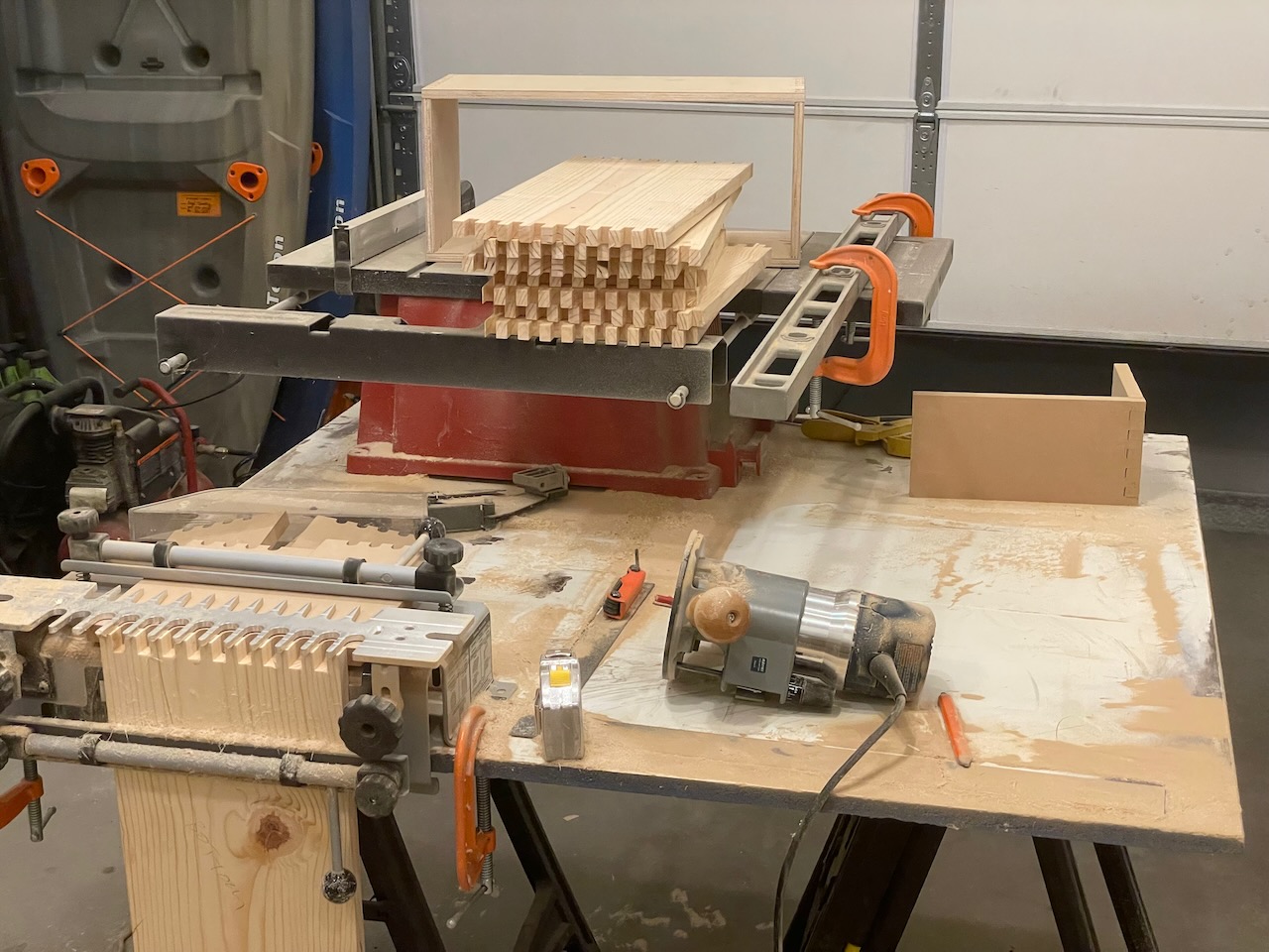
I’m not sure how old these wood clamps are. I inherited them from my grandpa and they’ve sure come in handy over the years.
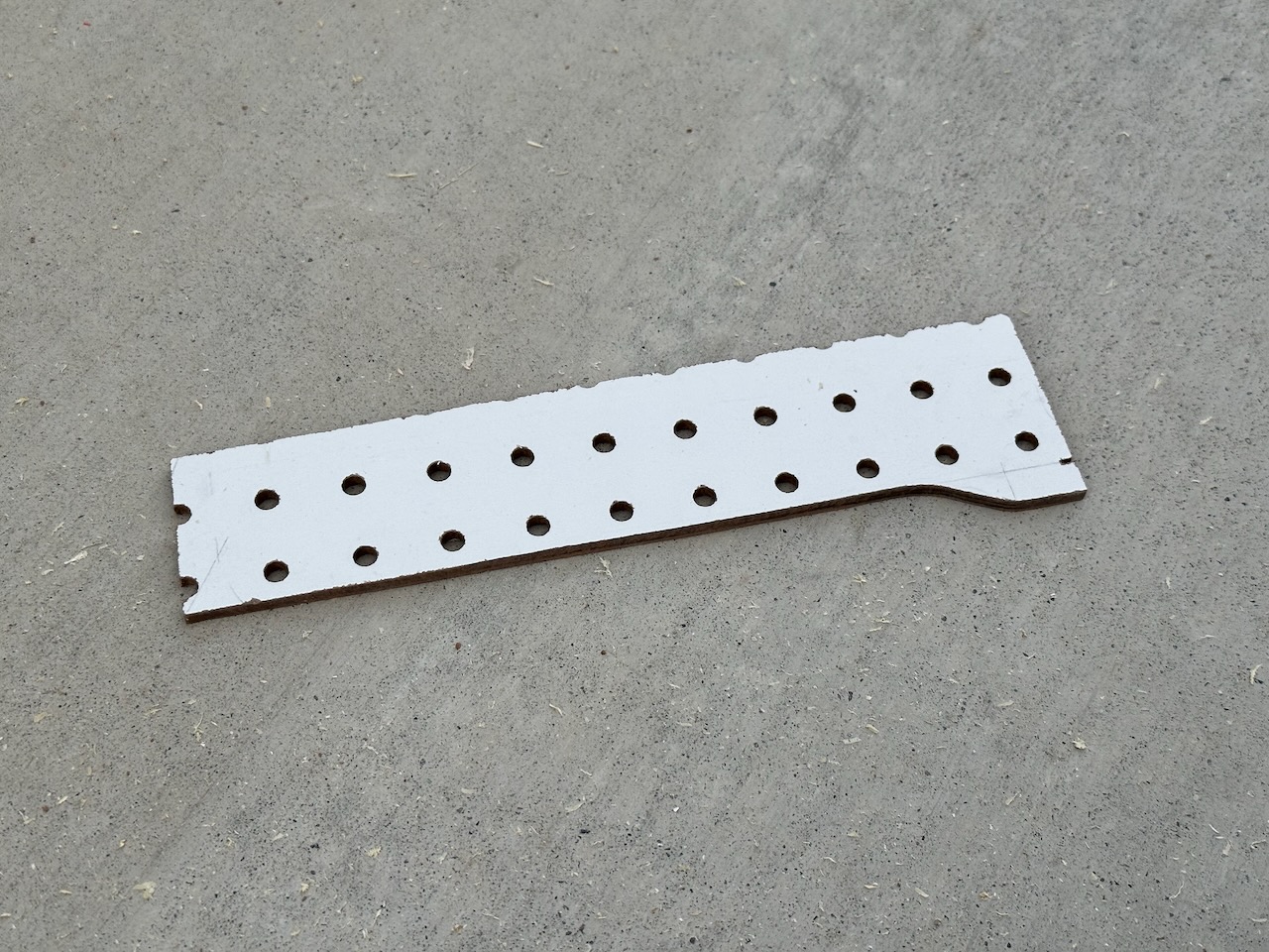
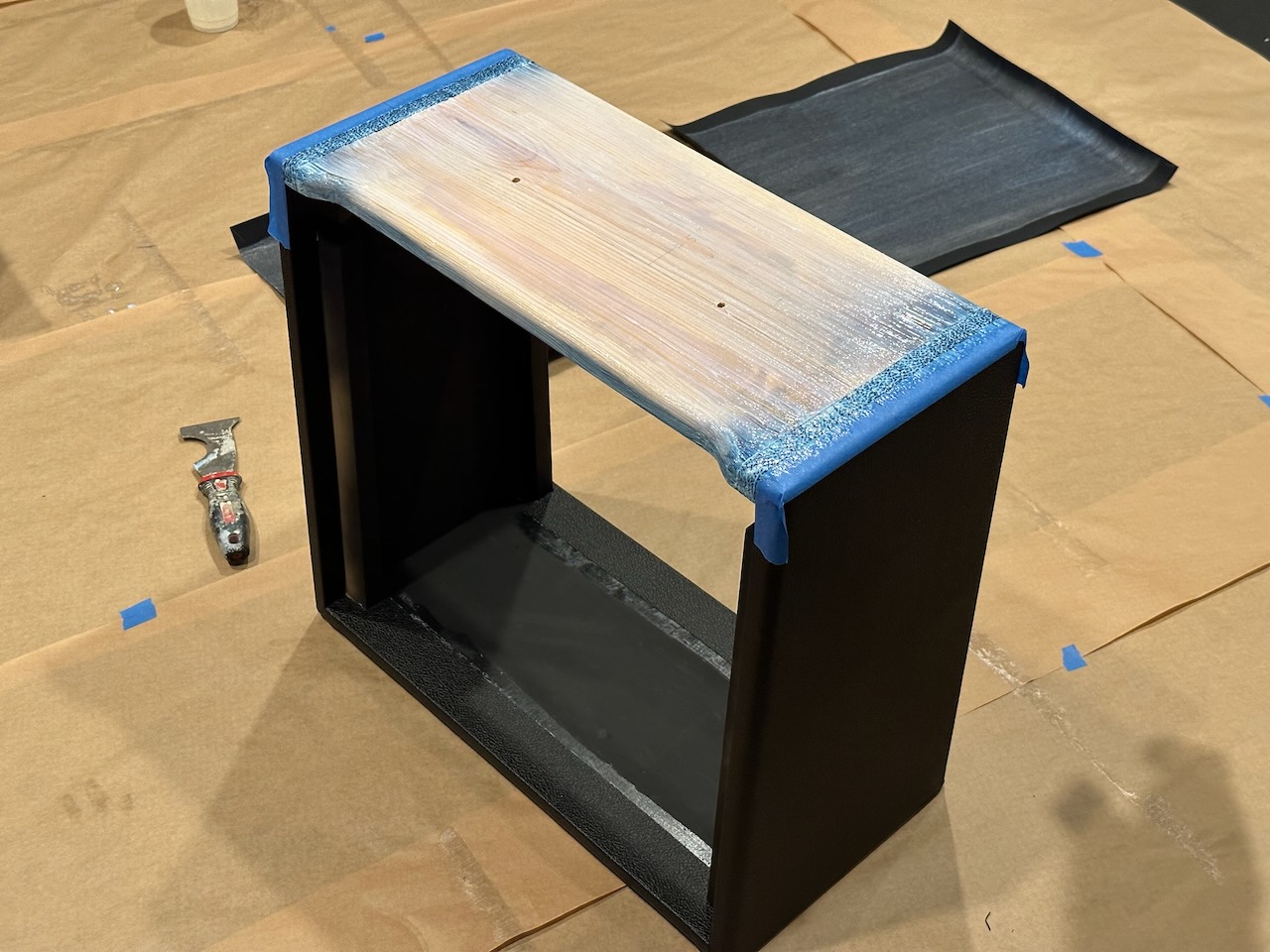
Since I made the chassis flat in front (not like the angled kind you’d normally find in a Fender amp) I wanted there to be a reveal at the top of the cab. I used a small piece of peg board to make a template. I flipped it over for each side so the router would make the same shape.
Here’s a picture of them after finishing the top cutout and rounding the edges with a 1/2” roundover bit.
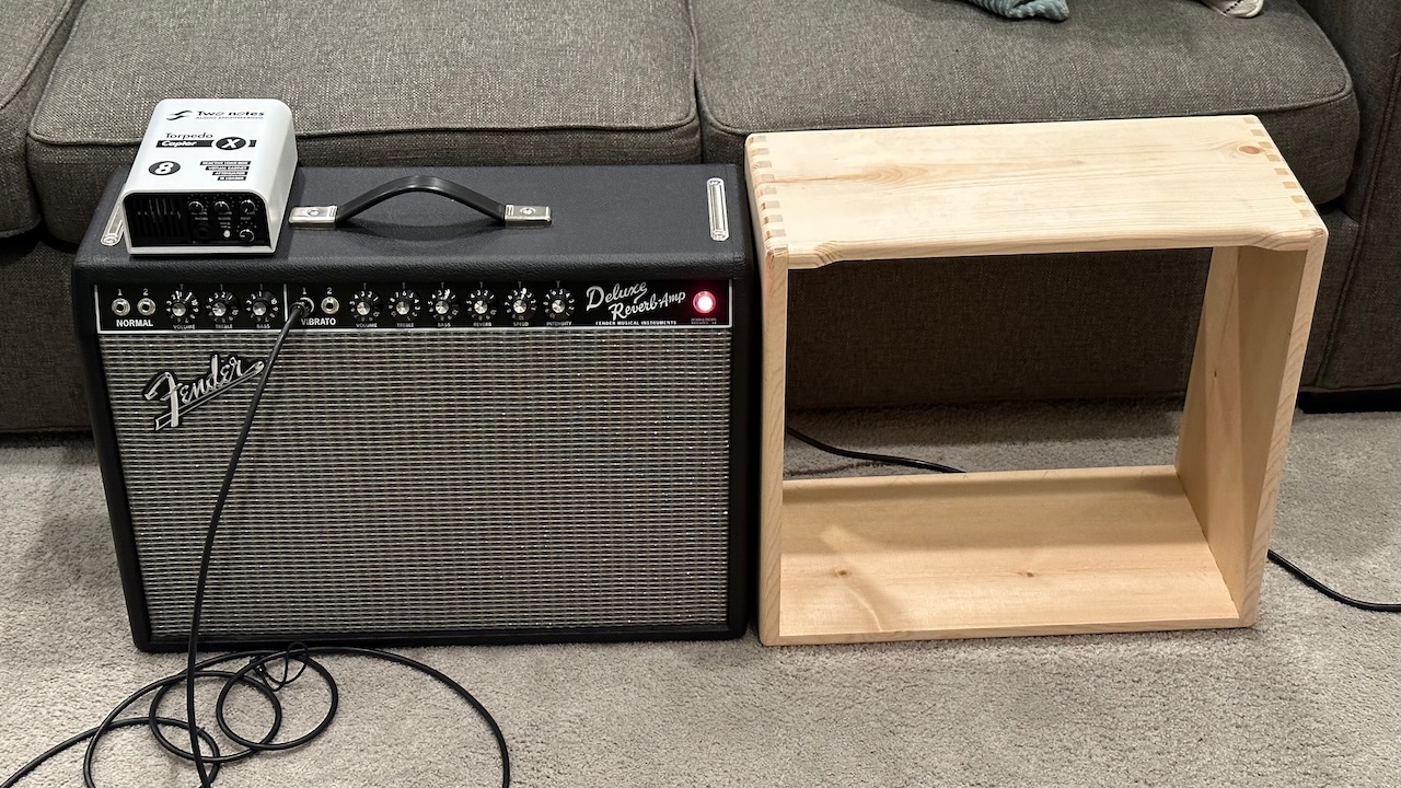
Just checking the size in comparison with a Deluxe Reverb. It’s just a little bit taller and definitely narrower.
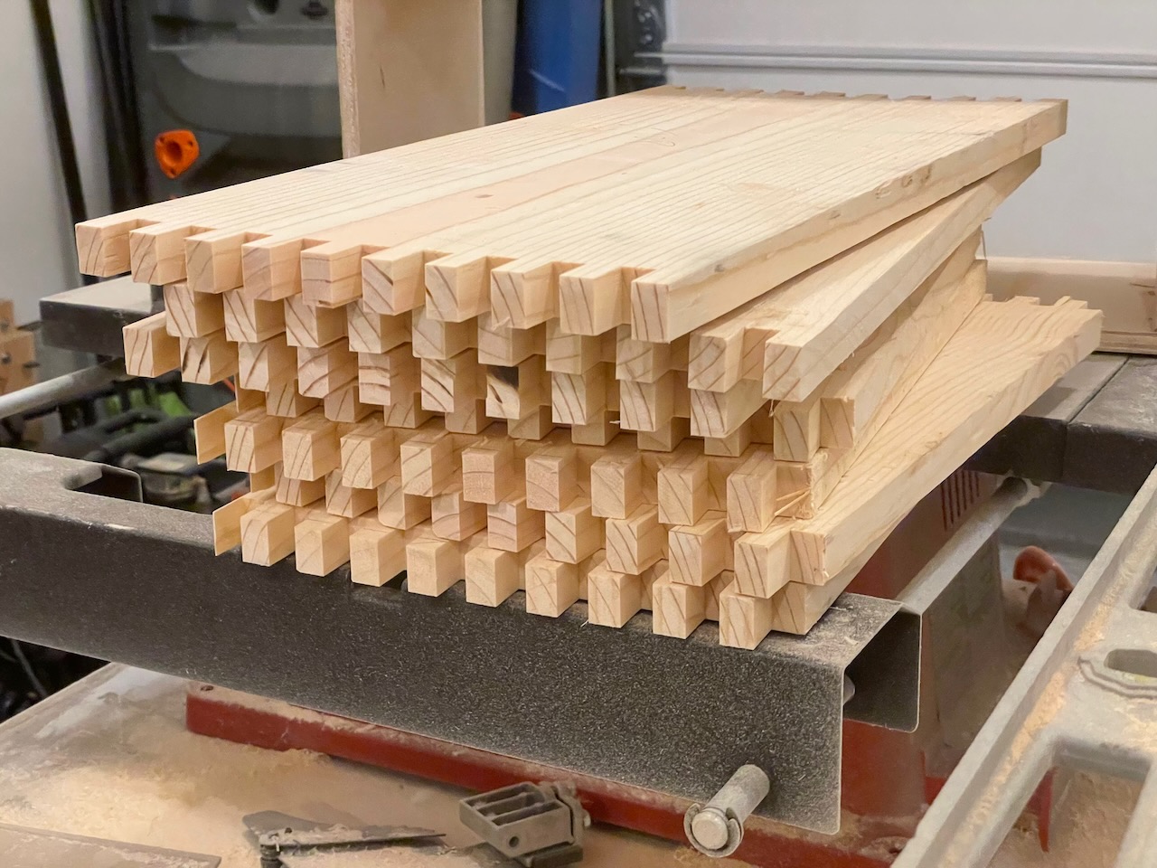
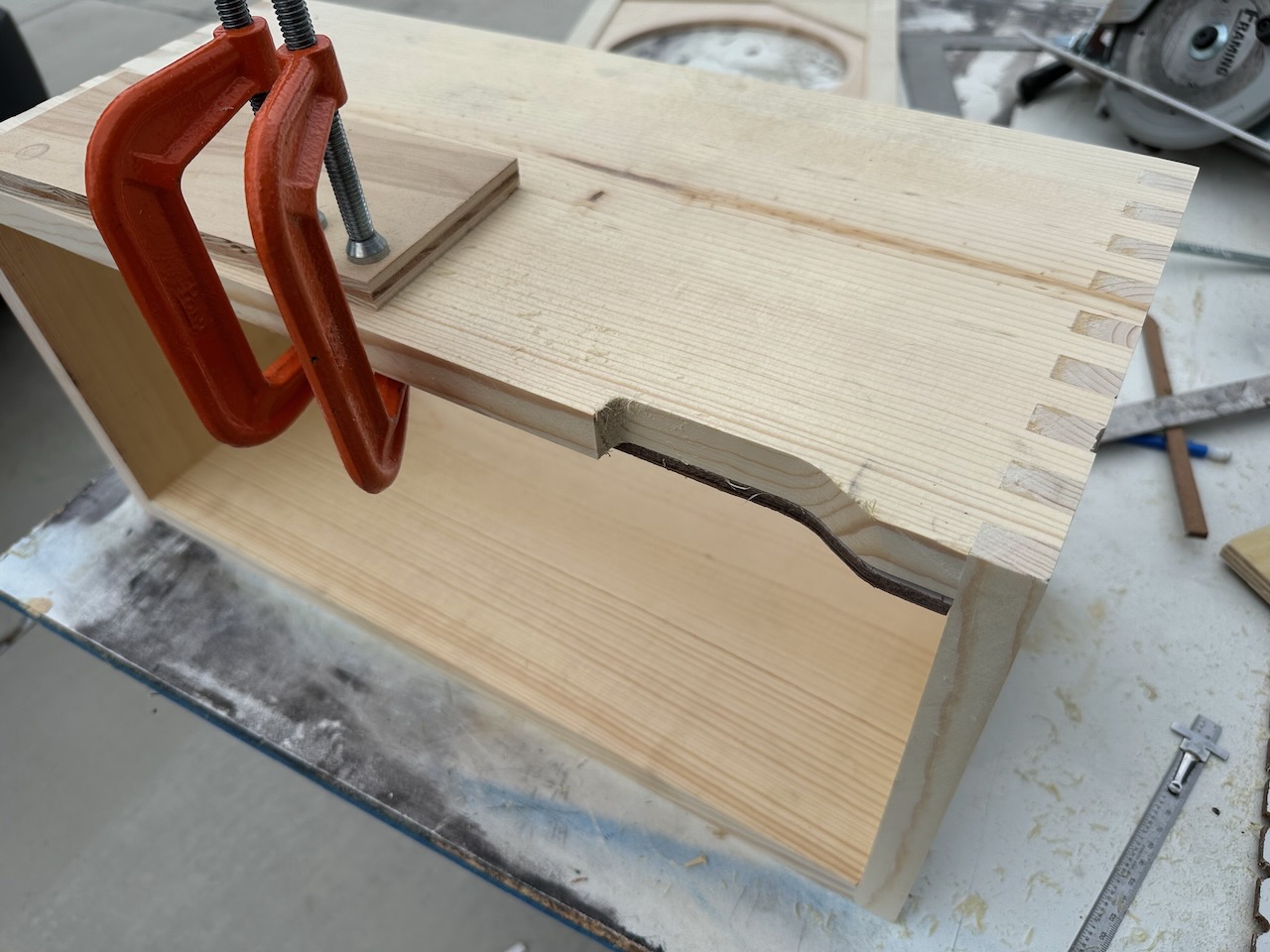
While building previous cabinets I learned that it was better to make the fingers on the box joints just a tiny bit longer and sand them down (as opposed to having to fill the holes with wood putty if they turned out too short). What I forgot to account for is that it would make the inside dimension of my cabinet a little bit smaller. DOH! So, I had to adjust the width of my chassis.
I took the opportunity to flip the end pieces around to give me a little more room inside the chassis.
I like to spray the inside of my cabinets black. This is definitely a personal preference and I know some people like to leave the raw pine wood exposed.
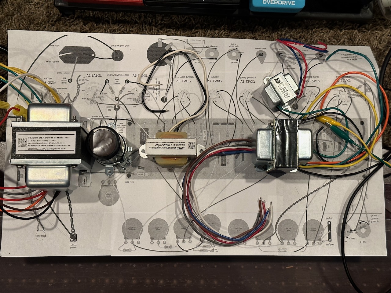
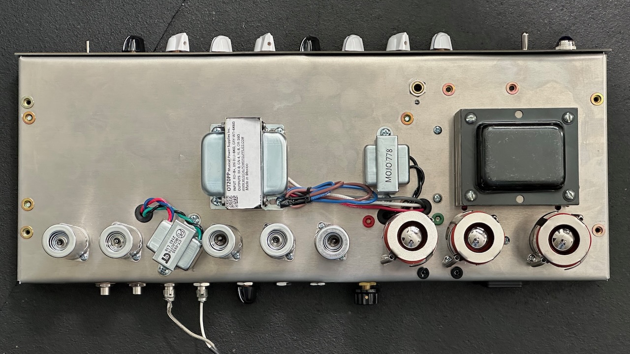
Here I’m getting a general idea of how the transformers will be placed on the chassis.
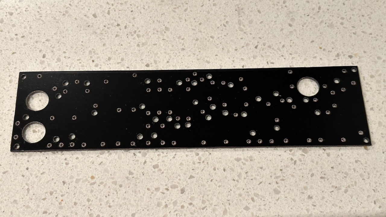
I bought a large blank G-10 epoxy board that I cut down to size and then sanded the edges smooth. Using a drill press for the turret holes makes it a much easier process.
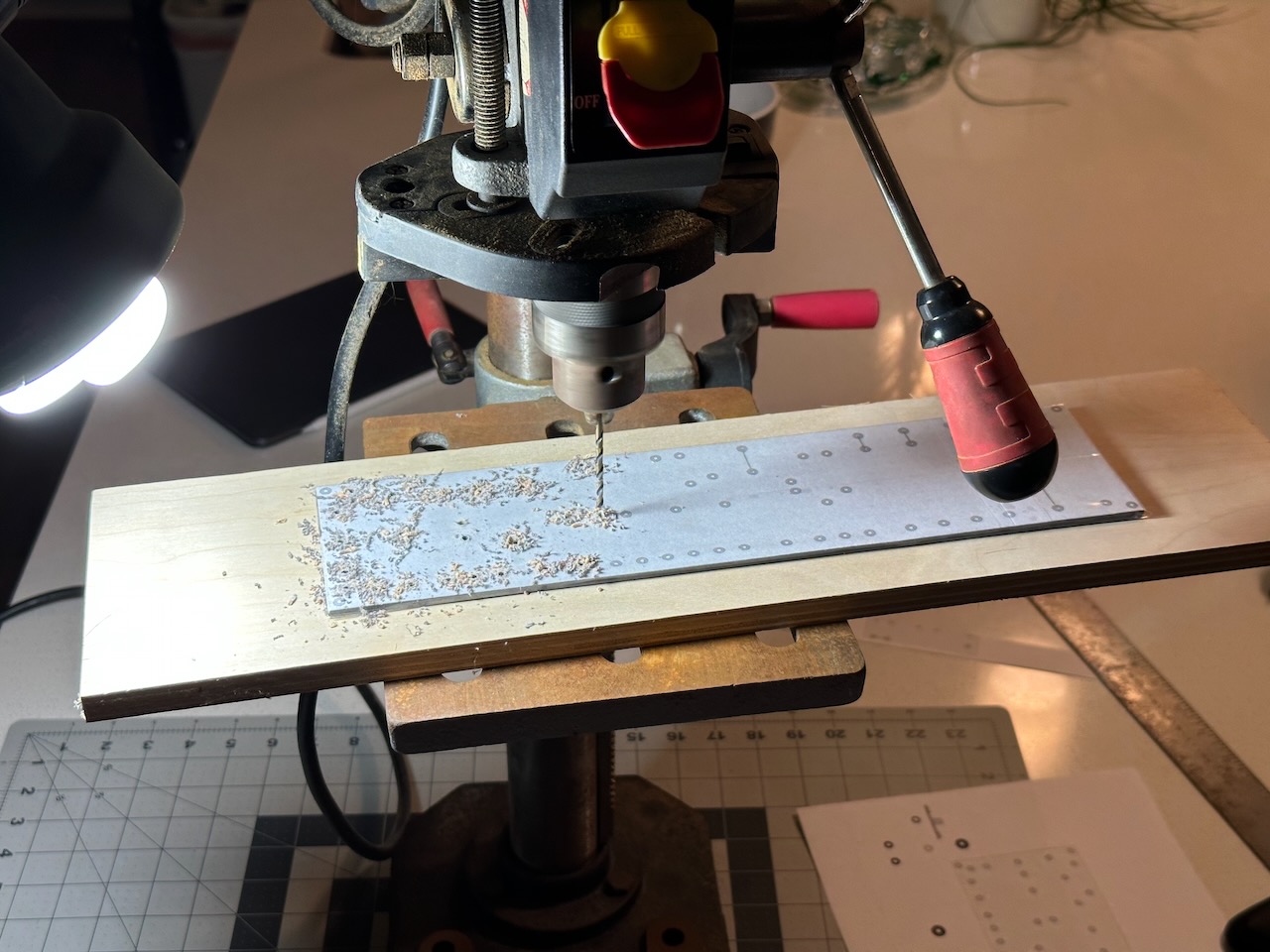
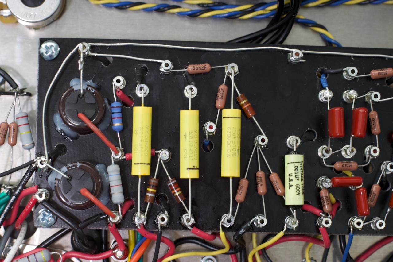
In the Mark II I decided to do a bunch of wire routing under the board. I’m showing both versions of the boards here. Later, I went back to Mk I and hand-drilled a number of oversized holes to re-route wires under the board. In Mark II I also used high-quality Nichicon radial filter capacitors and added them right in the board (that’s what the larger holes are for, which you’ll see later).
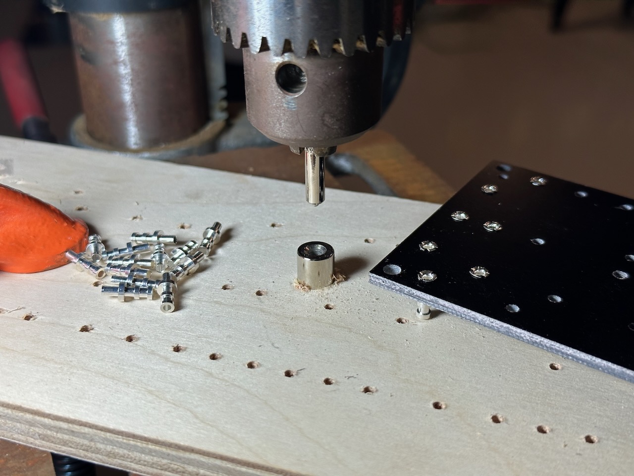
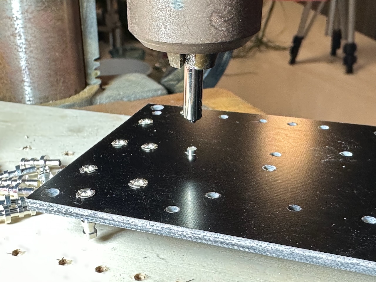
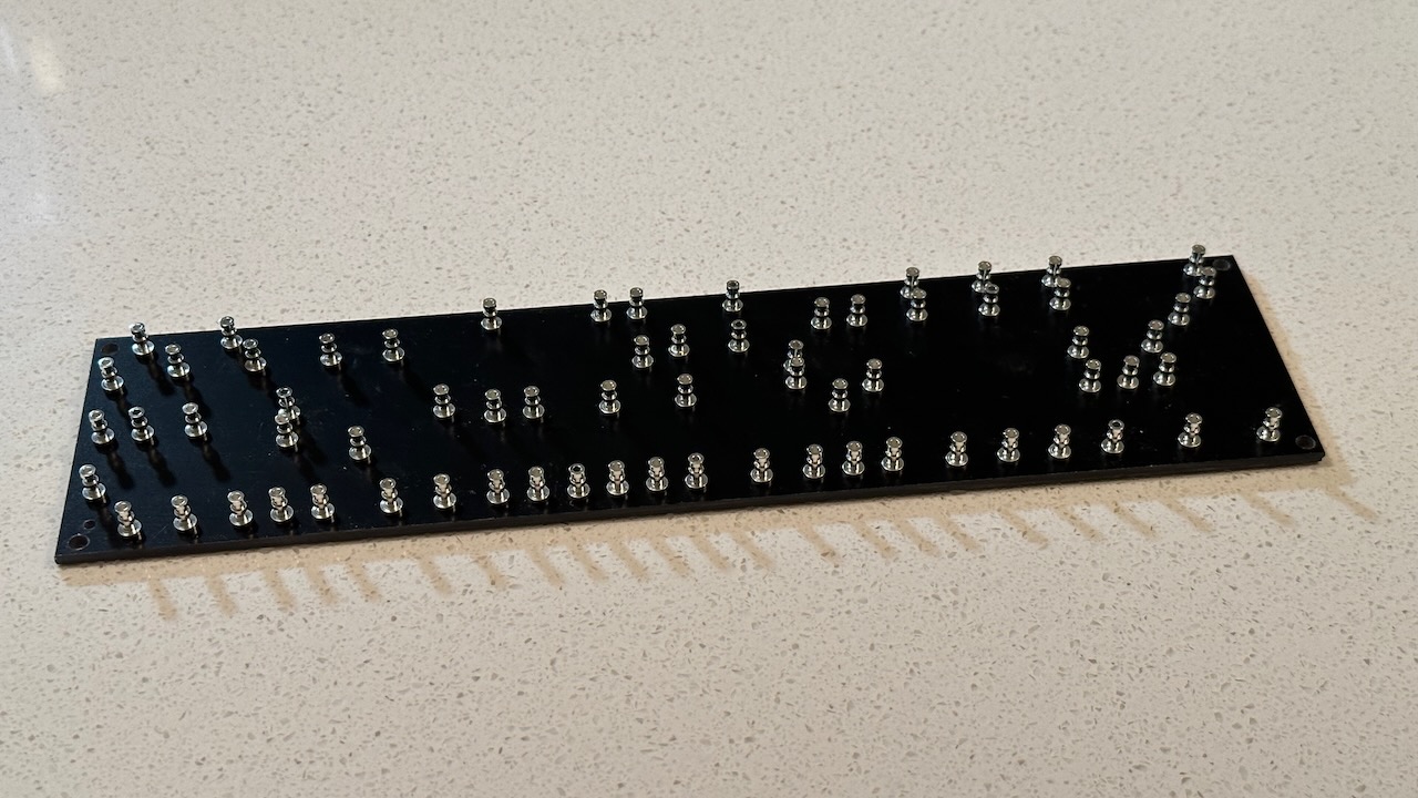
The drill press also helps easily seat the turrets in place.
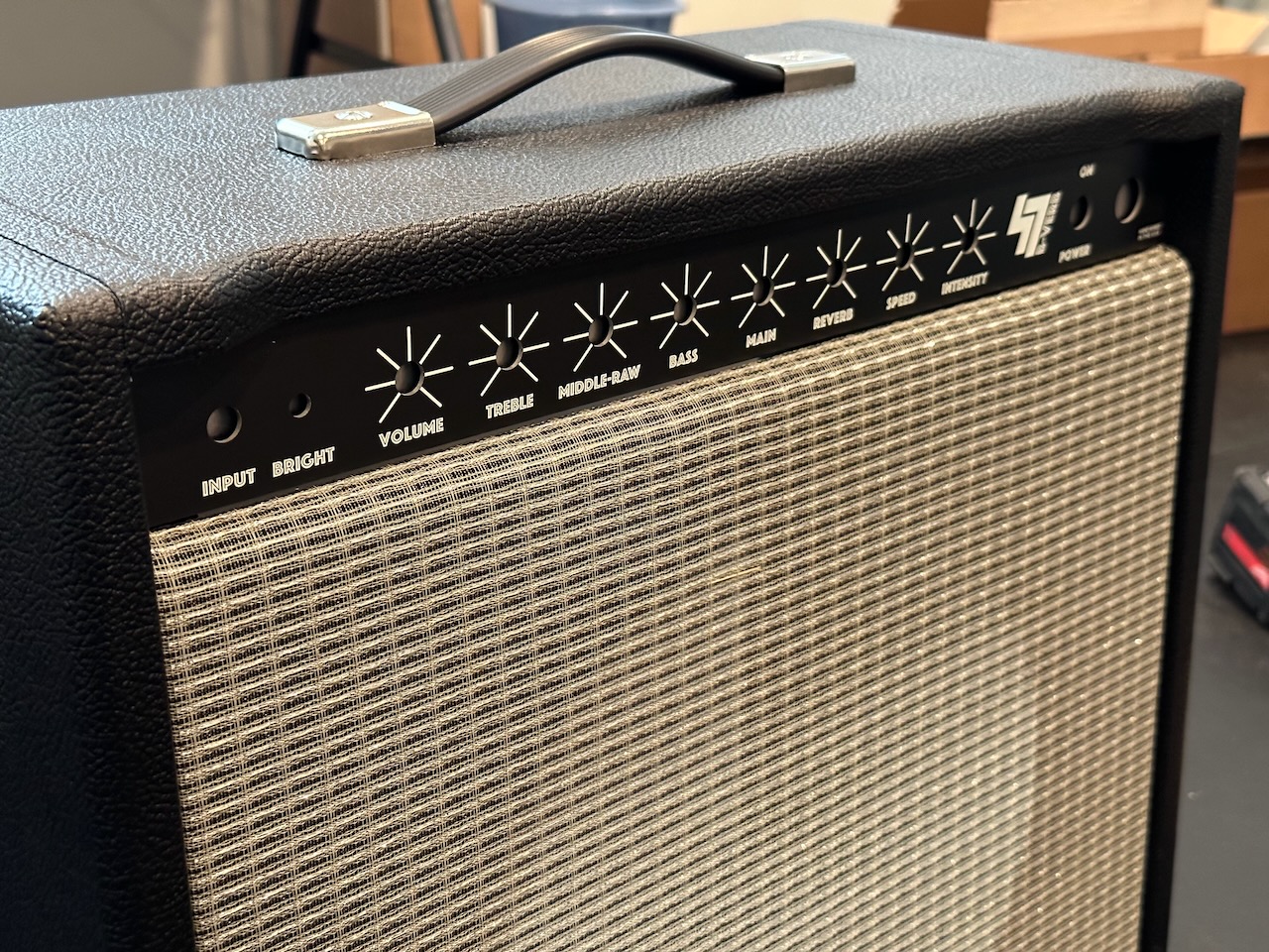
This was the first time I had used the Fender-style grill cloth. I think it turned out pretty well for the first time.
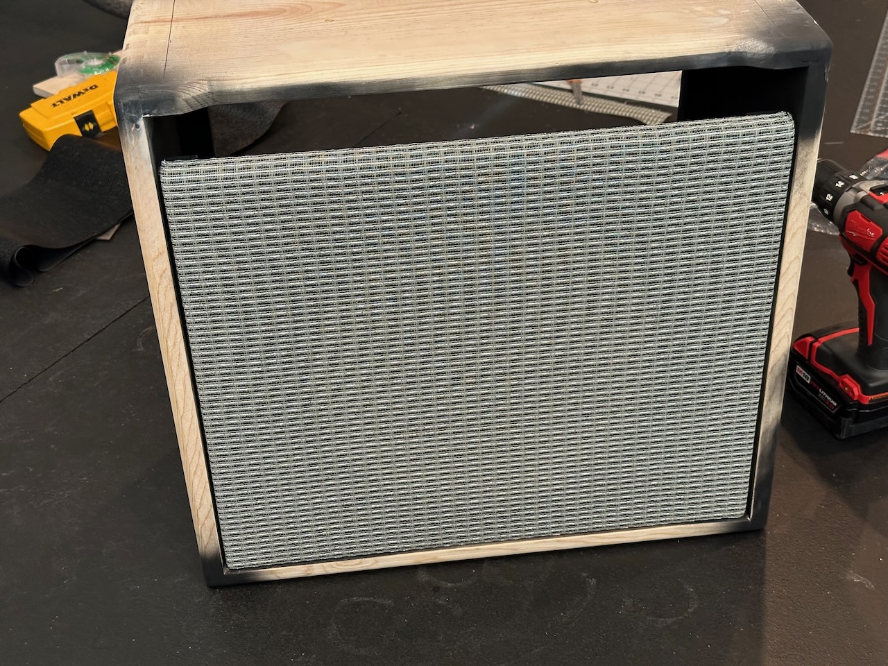
For the amp head, I used some left over salt and pepper style grill cloth so it’d match my Marshall-style 1x12 extension speaker cabs.
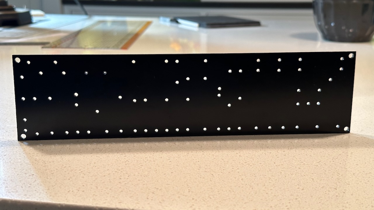
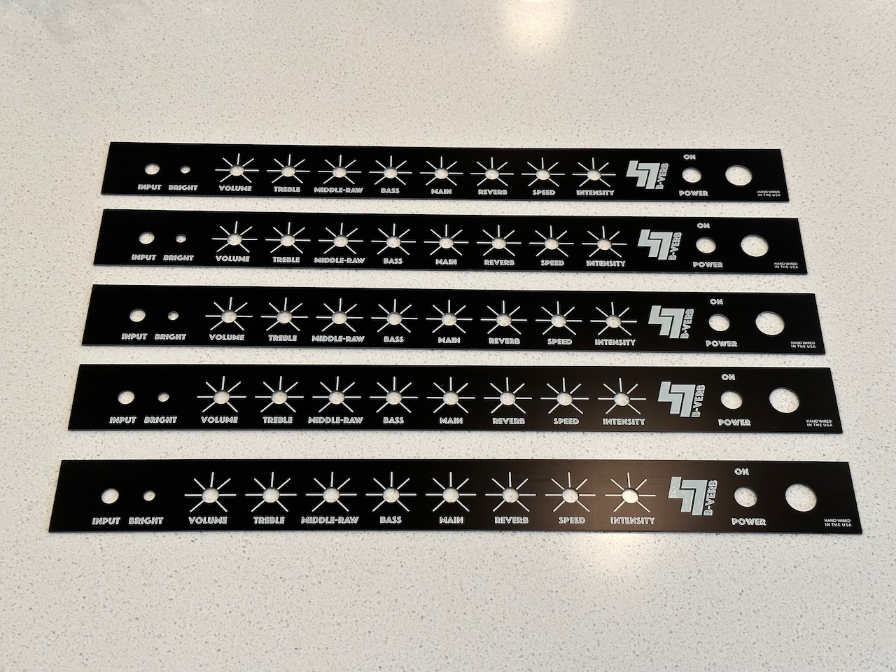
One other thing that inspired me to build the Mk II is that I had plenty of face plates. I stumbled across a tutorial on YouTube on how to build your own faceplate using software used for designing printed circuit boards (PCB). As a bonus, I was able to order prototypes of these boards from jlcpcb.com. It was a whopping $18 to get them. The minimum order is five and it only took a couple weeks for them to ship them to me. I’ve got three more … anyone wanna commission a B-Verb Mk III? :)
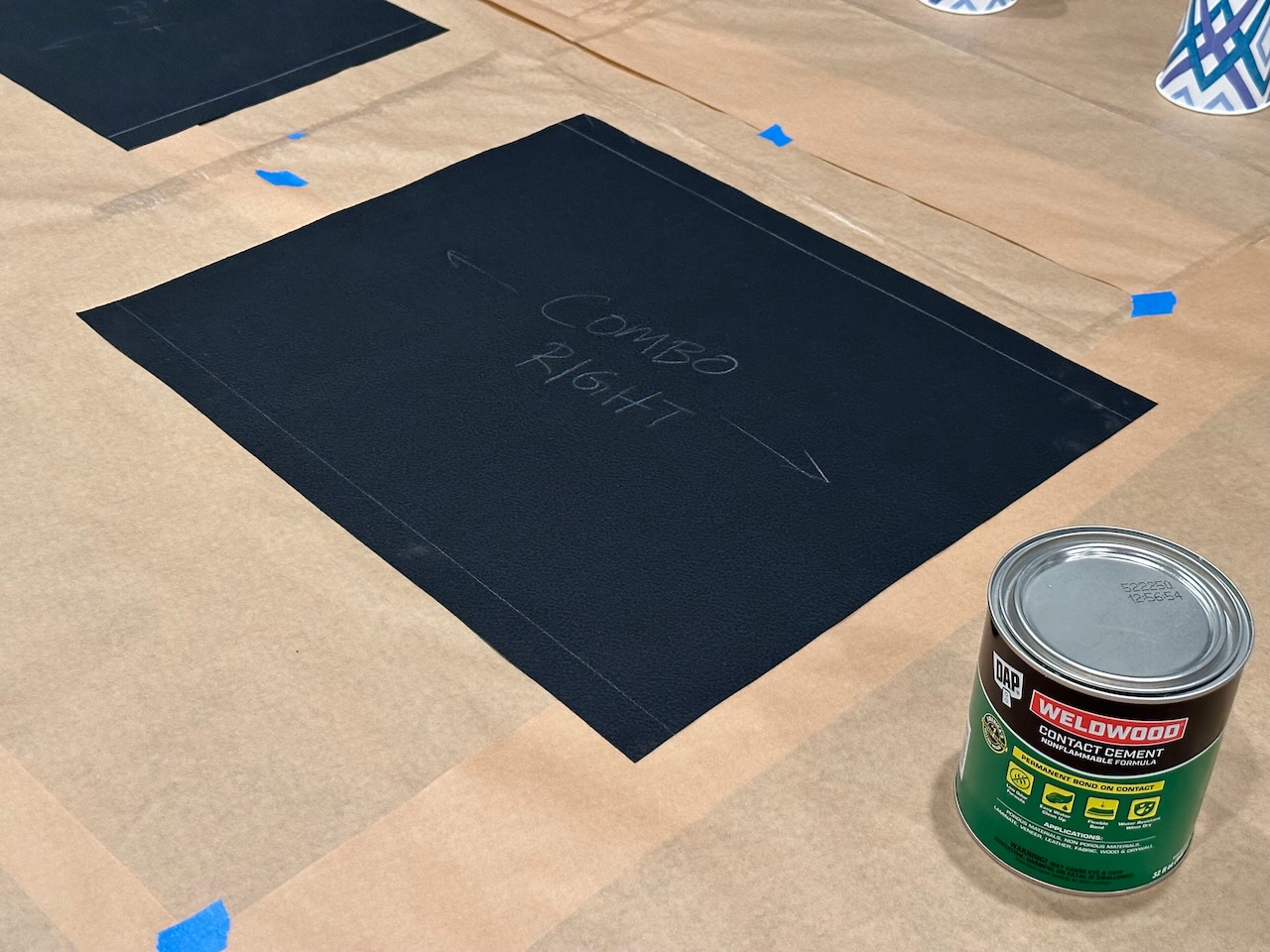
In my earlier amps I made the mistake of going way too cheap and I used vinyl flooring adhesive for wrapping the tolex. It only mostly worked. It never quite dried and just was generally not a great idea. This time around after reading a bunch of different reports, I decided to go with contact cement. Since it was the middle of winter I went with the water-based stuff so I could do it indoors without making the whole house smell horrible.
For these cabs I went with a four-piece tolex job just like most Fender amps are done. Another trick I had previously learned is to make sure and not stretch the tolex too much — or it can end up shrinking as it dries and cools. You just have to be careful not to stretch too much, especially when using a hairdryer or heat gun to help make the tolex more pliable.
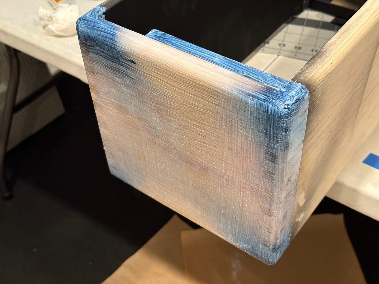
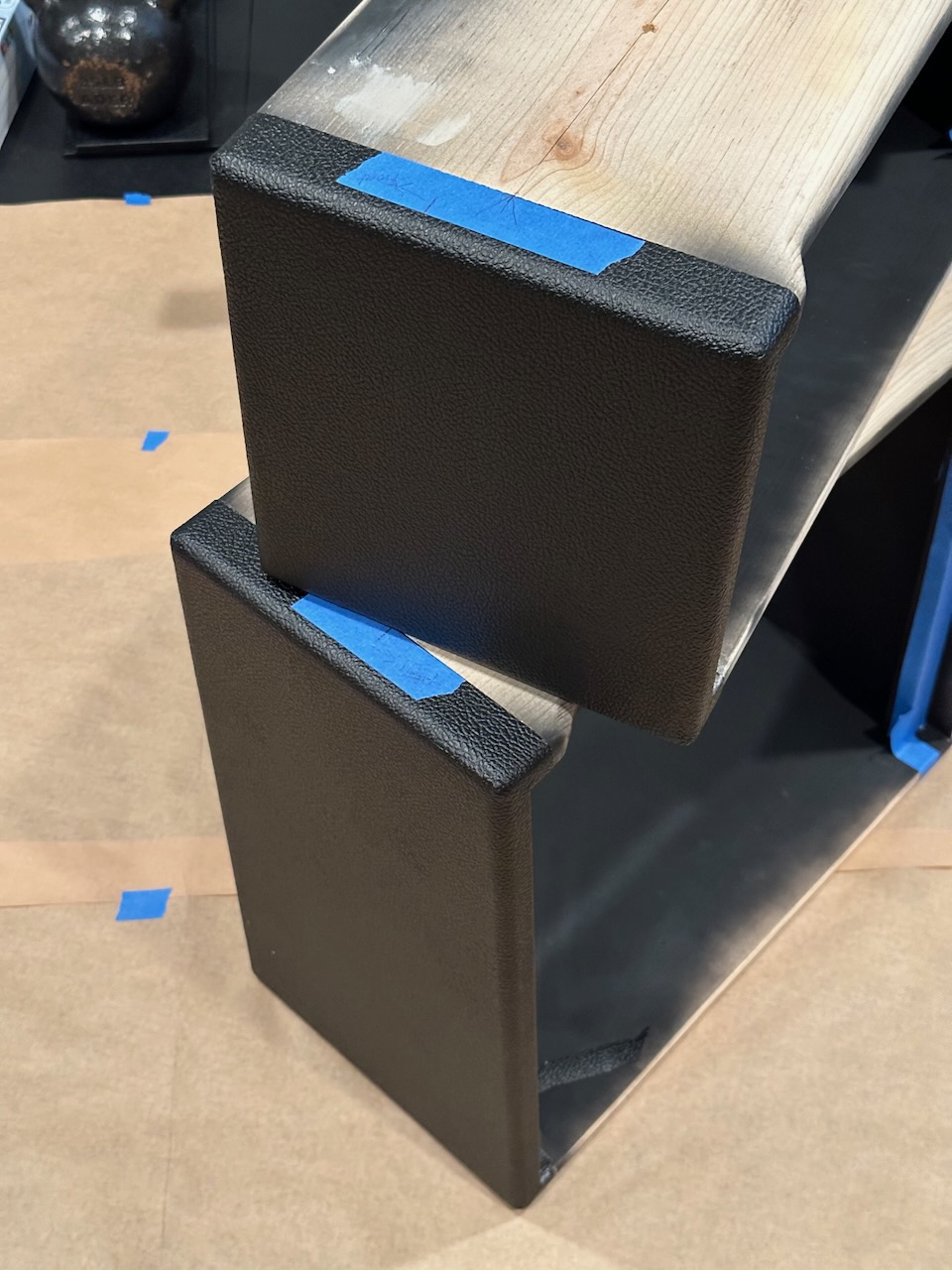
Here are a few pictures of the tolexing process. Even though it takes a while, I actually like doing it and I think they turned out a lot better than I had hoped. The water-based contact cement worked extremely well and is still holding up great.
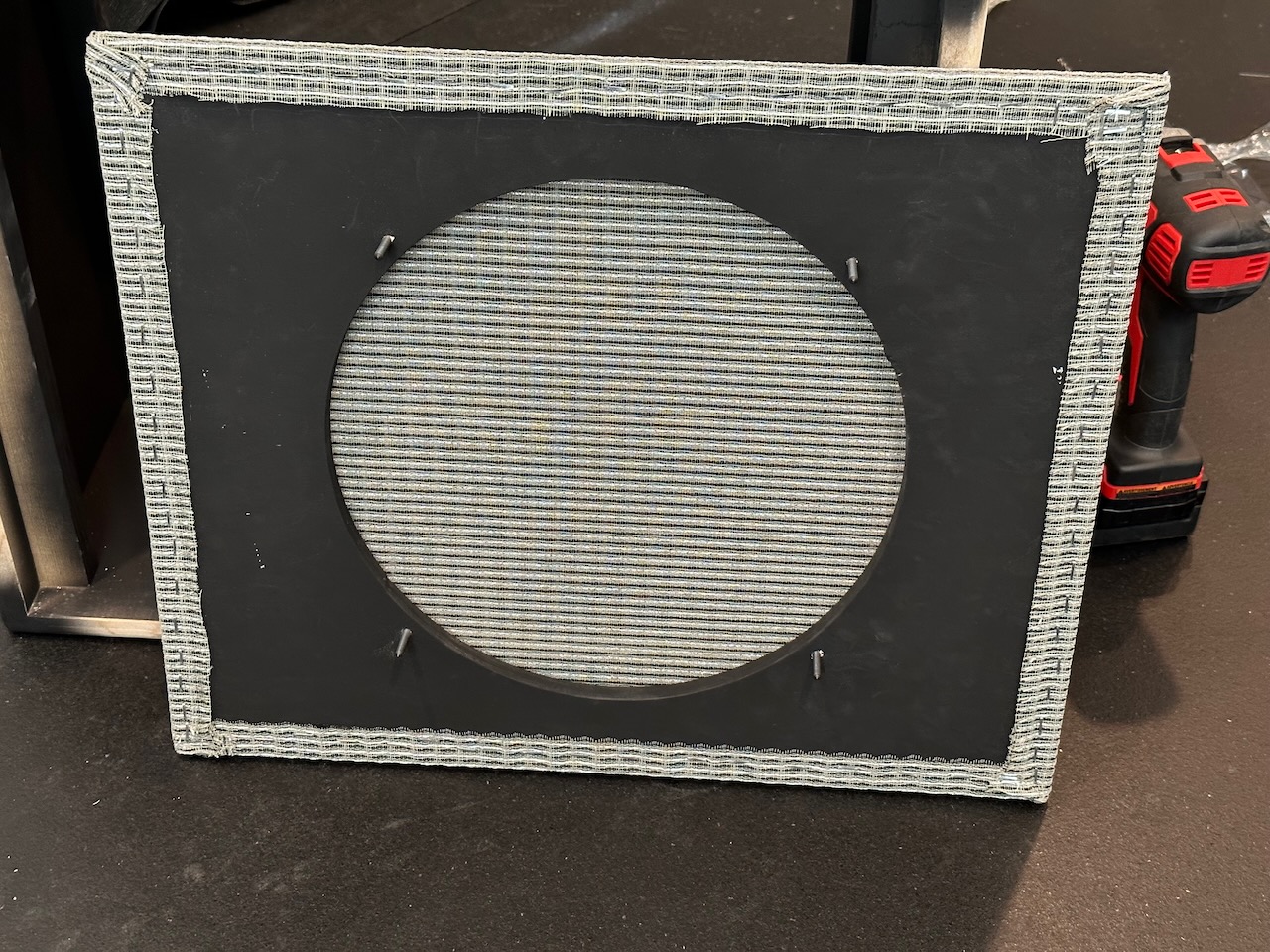
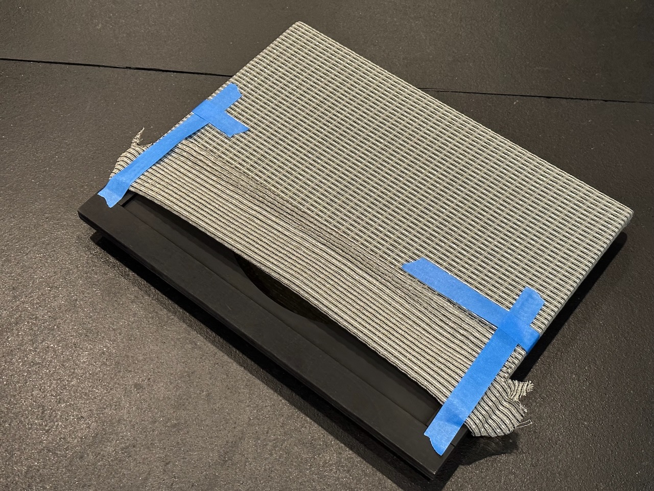
There were a few hiccups along the way. One of them was that I didn’t make the face plates tall enough. My original plan was to have the grill cloth butt up against the bottom of the face plate. What I should have done was to make the bottom of the faceplate even taller so that there was plenty of room for the grill cloth (with a little play). Instead, it was just too close for reading the labels.
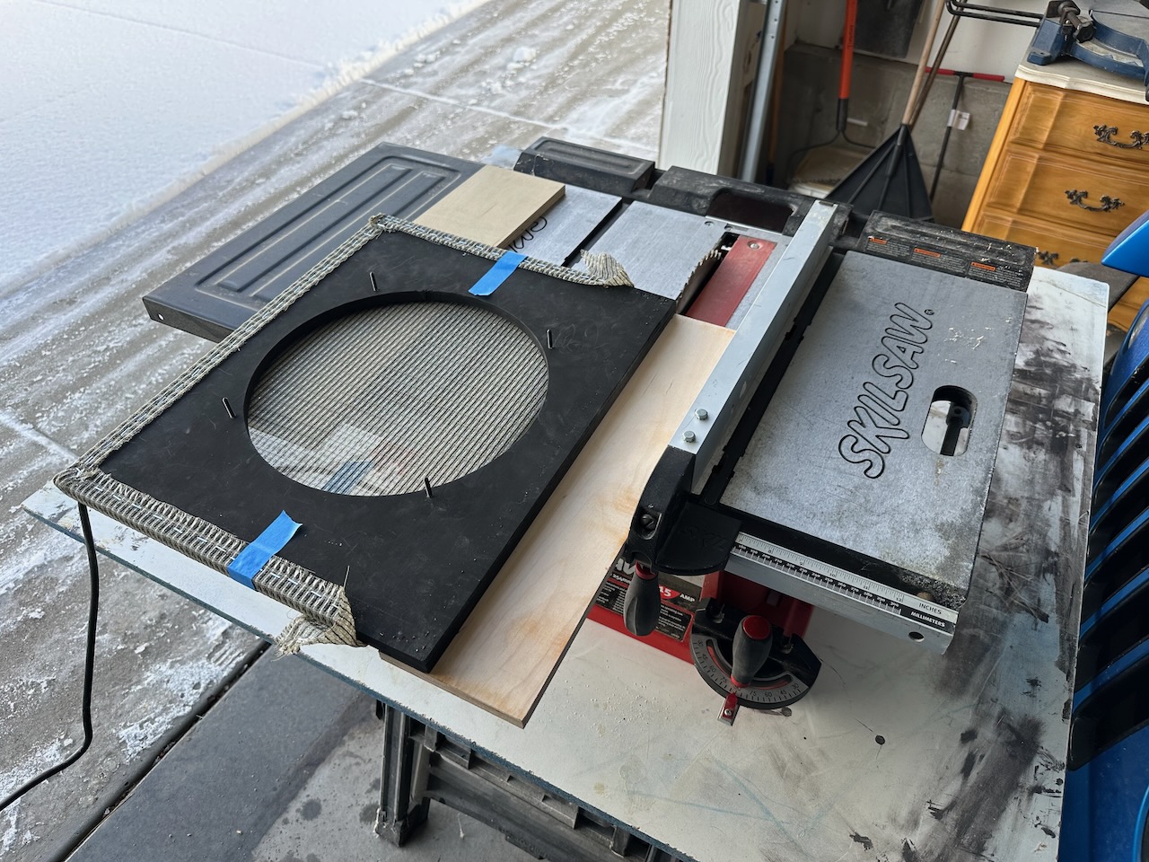
So, I ended up making a last-minute adjustment by making the grill cloth panel slightly smaller. I did a gutsy move hoping I wouldn’t ruin the grill cloth. I temporarily mounted another piece of wood so I could send it through the table saw and fortunately it all worked out!
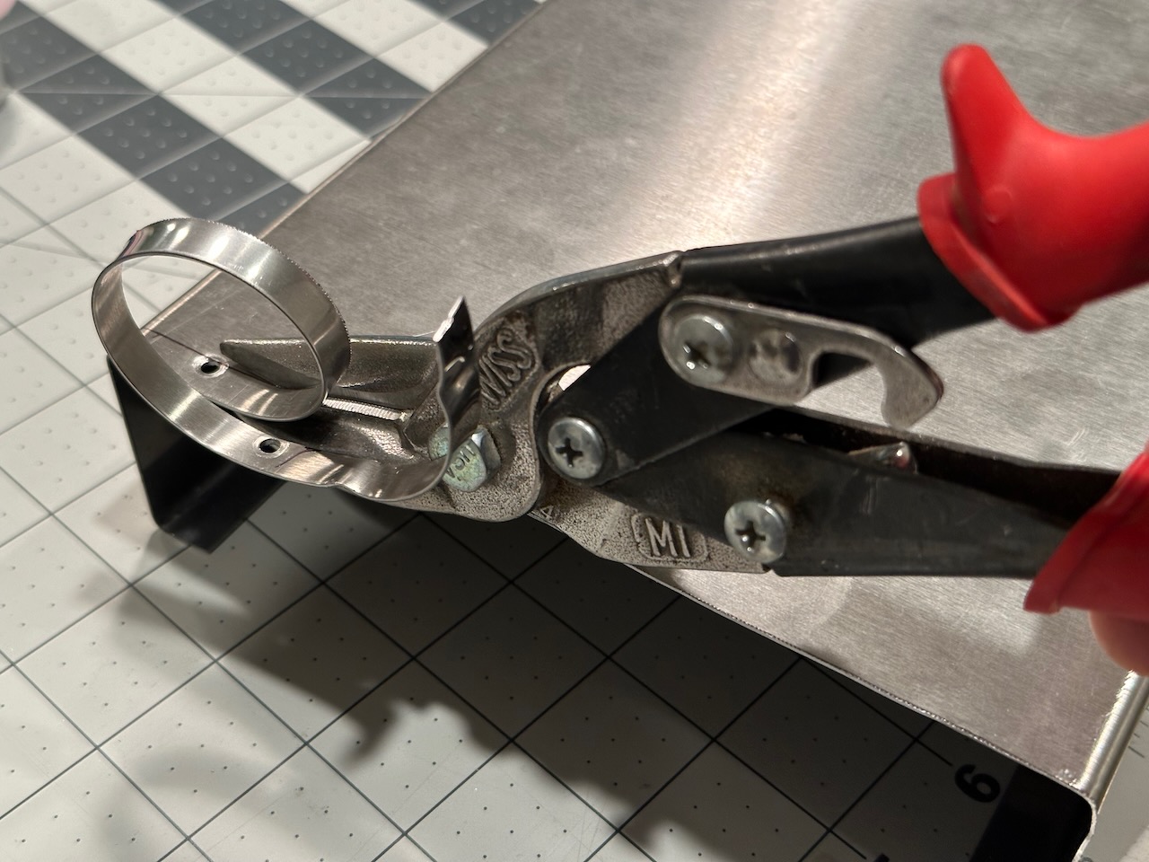
As mentioned earlier, drilling holes in stainless steel, particularly the larger holes with a step bit turned out to be really difficult. Since I didn’t have a set of punches, I finally ended up just using my tin snips for making the holes for the octal sockets and cap can (the Mk I orignially used a JJ 40/20/20/20 cap can, but I later switched to Nichicon radials).
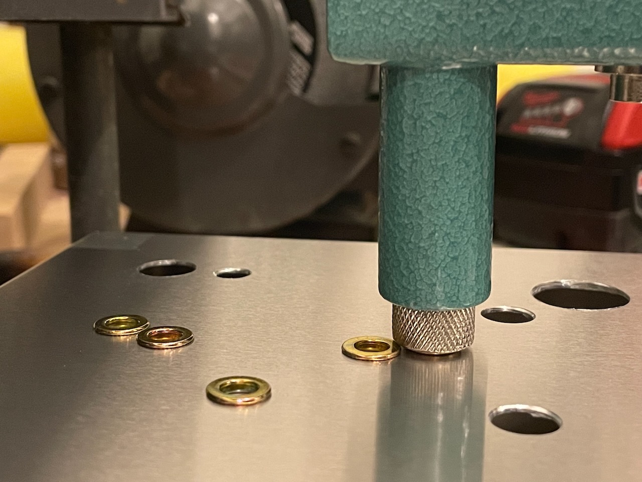
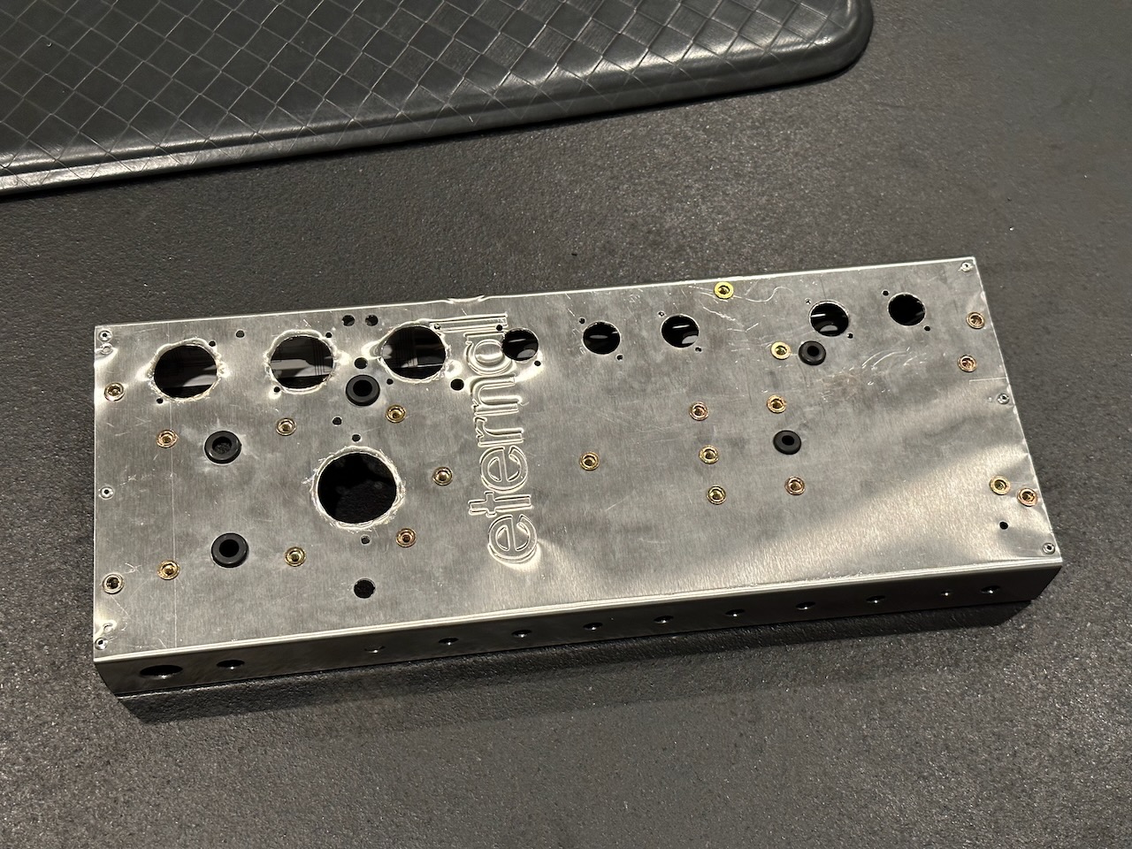
In my earlier amp builds I used rivet nuts (rivnuts) as recommended by someone on the tdpri.com forum. I really like them because I can easily mount transformers almost anywhere without worrying about having to access underneath the board to undo or fasten a nut. They also make great board mounts because they automatically hold the board up away from the chassis a little bit and with a 1/4” nylon standoff the board has great clearance away from the chassis.
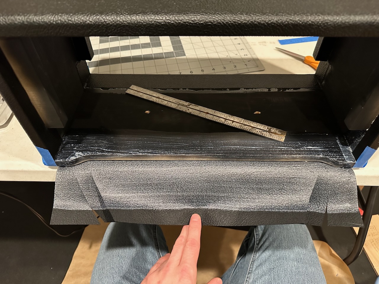
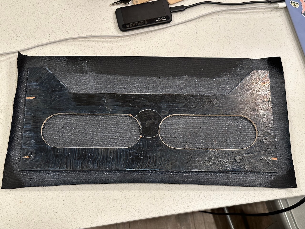
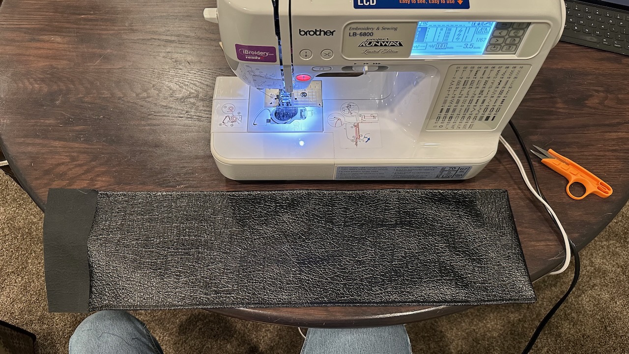
Part of the goal for completing this project is to do as much as possible from scratch. That included sewing the reverb tank and padded amp dust covers!
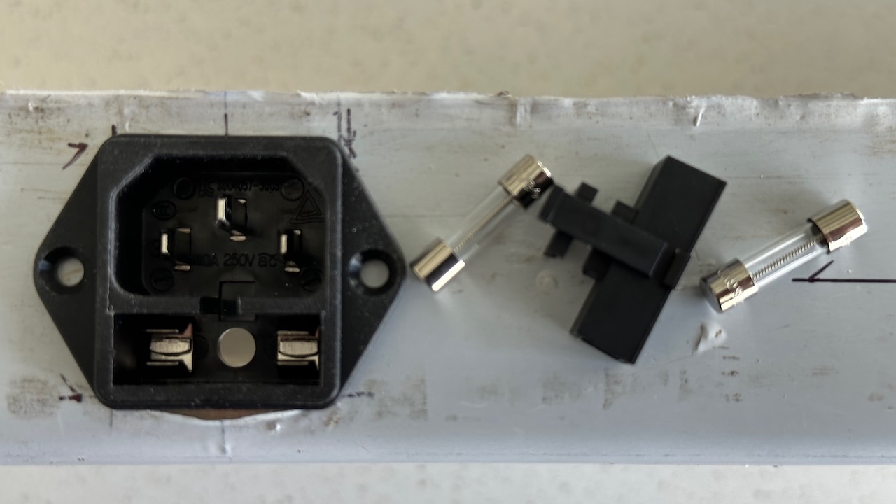
In the Mk II I used a much superior IEC socket that has a built-in fuse holder. Since there’s not a lot of room inside the chassis this works perfectly. Plus, there’s a spot to store a spare fuse in there!
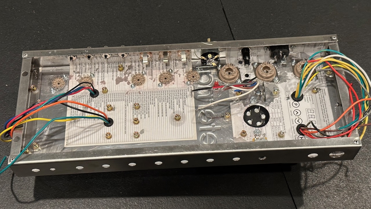
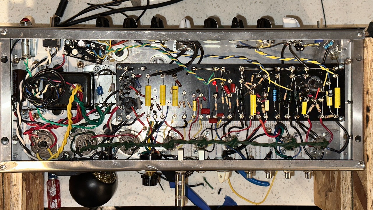
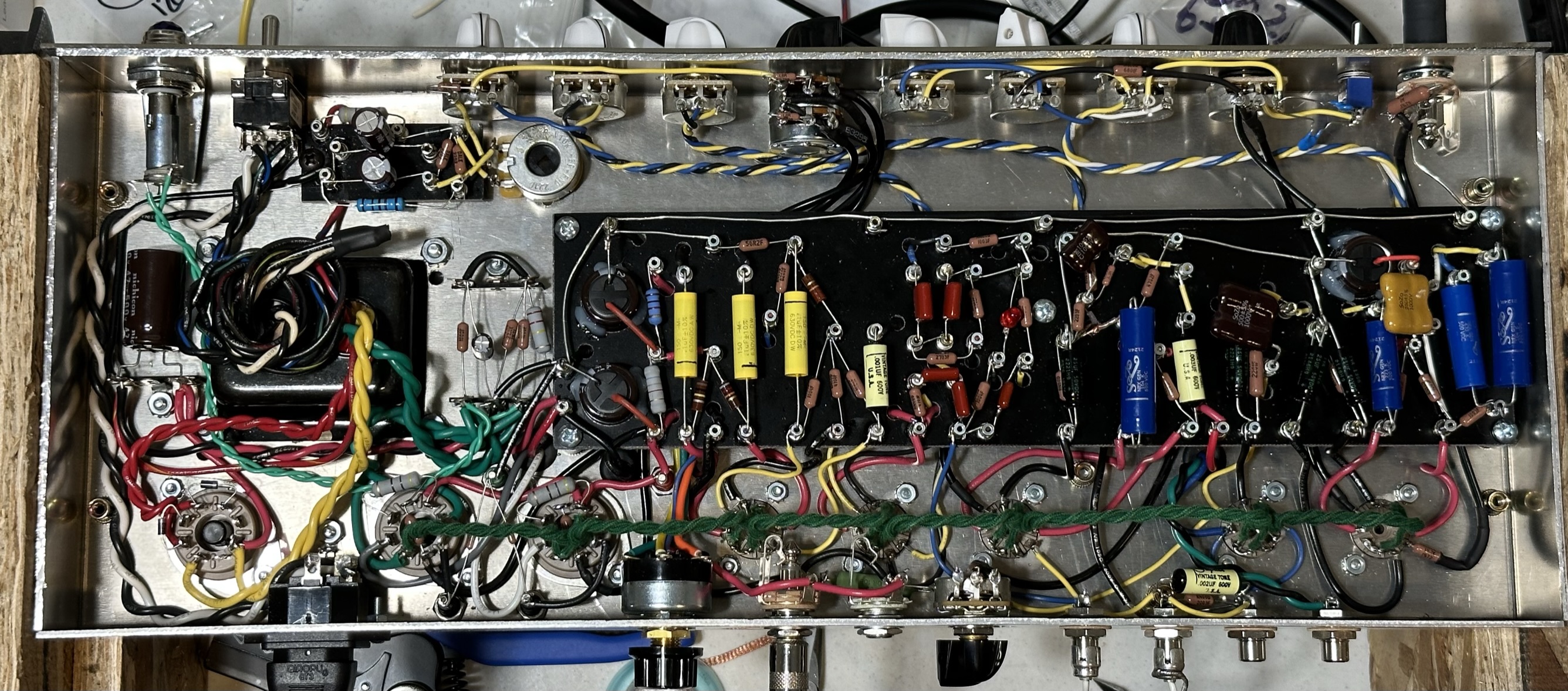
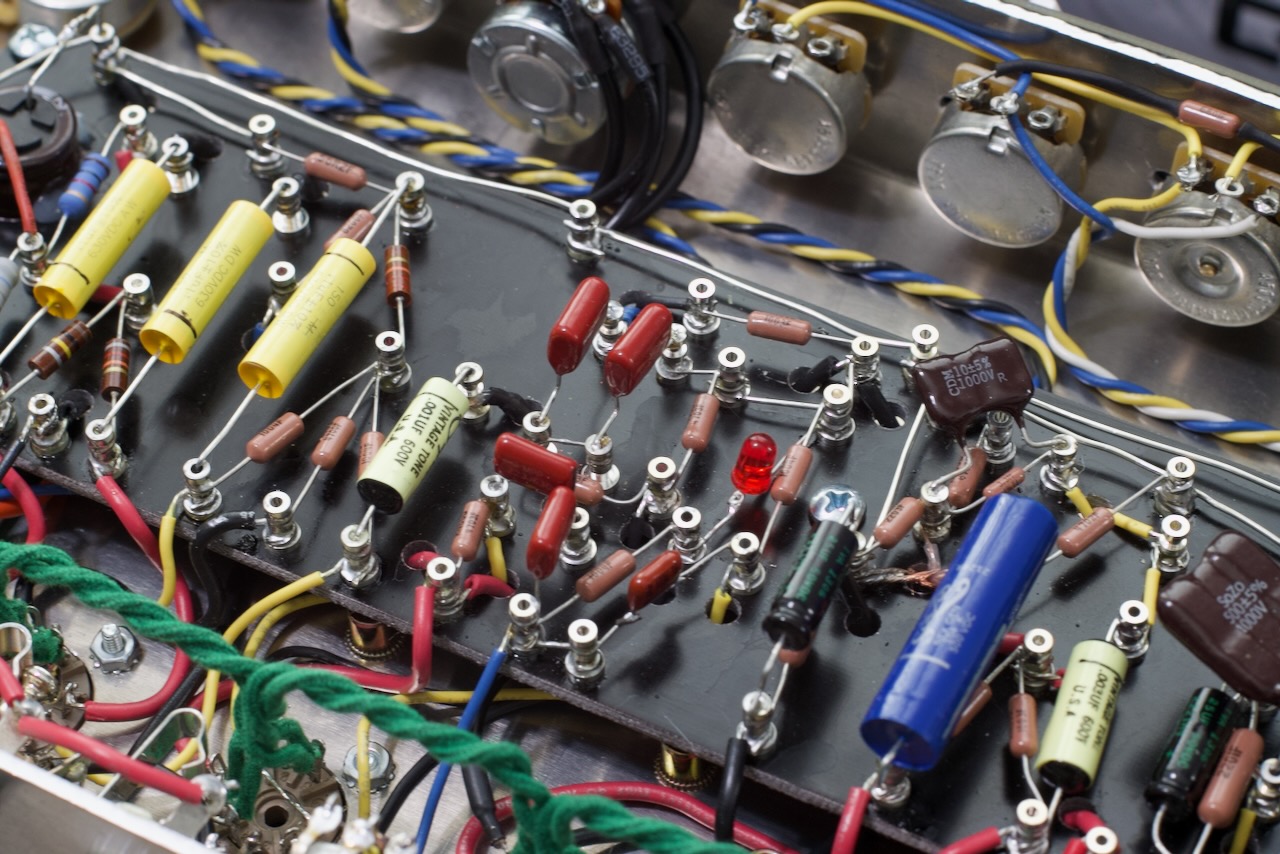
I won’t go into depth on wiring and soldering, but here are a couple of gut shots of the Mk I and Mk II. The Mk II is noticeably cleaner. That’s mostly due to the fact that I planned out the layout with some improvements on the Mk I. I’ve since updated the Mk I after-the fact to try to match some of the layout decisions.
One of the main things I changed in Mk II’s layout is that each stage of the circuit grounds to the negative terminal of the filter capacitor of that stage. In both amps there is only one circuit ground and that’s at the input jack. I guess initially I had the four RCA jacks at the back isolated and so the one circuit ground was literally true. I’ve sense gone back to having the RCA jacks connect at the chassis (was trying to do it more like what Fender did to see if that’d resolve some of the extra hum on the reverb part of the circuit).
I should have planned better in Mk II with the placement of the power transformer. It’s kinda close to the output tubes. But … it “works!”
The Mk I had a number of extremely difficult issues to track down after I built it (mostly dealing with hum and buzz). I learned a lot about tracking down noise issues. I should make a list of all the things that fixed noise issues in addition to the things I tried. It’d shock even me. Haha. I finally discovered one of my main hum issues was caused by me with a miswiring of the bias board. That took months to discover what it was!
Both amps use Mojotone’s Deluxe Reverb Power Transformer and seem to perform really well. Using an oscilloscope, an adjustable dummy load that I built, and a 1kHz sine wave, I took some output power measurments. They both have 25 Watt output transformers, but I’m calling them 22 Watt amps. These are measurements taken right at the point before the signal goes into distortion. Both amps have 454V on the output power tube screens and are biased at 65% plate dissipation at 20mA. I’m using JJ 6V6S power tubes.
| Output Ohms | Mk I | Mk II |
|---|---|---|
| 16 Ohms | 21.1 Watts | 19.5 Watts |
| 8 Ohms | 23 Watts | 21.4 Watts |
| 4 Ohms | 24.1 Watts | 22.8 Watts |
In the Mk I the components I used were generally less expensive - mostly cheap carbon film resistors I bought in a pack from Amazon, some Mallory 150 tone capacitors, etc. In the Mk II I wanted to see what, if any, effect there would be by using the more expensive caps, SoZo Blue and Jupiter – and Vishay Dale resistors.
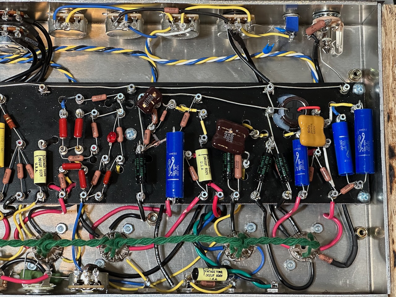
I can’t really tell any difference when I test them through the same speaker. So I’m not sure that the more expensive components would be worth it in any future builds. They definitely look cool.
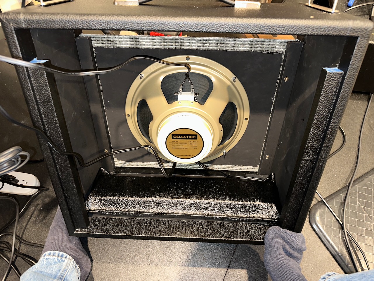
The Mk I combo has a Celestion Creamback Neo 12” 8 Ohm speaker. It’s not as efficient as the 1x12 speaker cab I usually use with the Mk II head (a Mojotone Greyhound 12” 8 Ohm). The Greyhound has more of a bass response than the Celestion Neo but I frequently find myself flipping my opinion between which one I like better - though lately I prefer the Greyhound.
I discovered a trick from Hoffman (el34world.com) where you can use a red-colored LED in place of the resistor and bypass capacitor on the cathode connection to ground on the tremolo circuit to help get deeper tremolo. I salvaged a couple of these LEDs from some old smoke detectors. It lives up to the promise and the tremolo can get nice and deep because of it.
With a desire to keep the self-noise (mostly hiss) of the amp lower, I followed advice to only use carbon comp resistors in the phase inverter and negative feedback tail resistor.
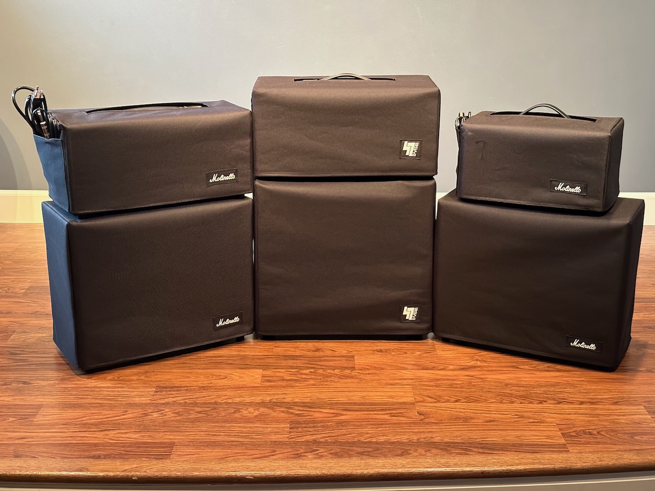
Here’s a couple of glamour shots of these two amps:
Videos and Audio Files
A timelapse of some of the wiring of the Mk II can be seen here:
Goofing around with the Mk I plugged into a Torpedo Captor X:
A short clip of using both amps and with a bass guitar as well. The audio isn’t as great with this one because it’s just recorded with an iPhone. For the lead guitar part I used a POD Go with a higher octave pedal engaged.
Additional videos and sound samples coming soon!
Special thanks to many very kind amp builders on the Telecaster Discussion Page Reissue’s DIY Amps, Cabinets & Speakers forum, formerly known as “Shock Brothers.” Along the journey of building these amps I posted (many) questions and their help was invaluable!
The length of this list is borderline embarrassing, but it’s proof how helpful this forum is!
- Repurposing a tankless water heater into an amp chassis
- Cap can instead of individual filter capacitors for a Blackvibe RR763 6V6 build?
- AmplifiedParts or Mojotone Tolex Glue?
- How to shape the cutout on the top of amp cabinet?
- Single-channel AB763 Build(s)
- B-Verb V2 DRAFT Layout Diagram (1-channel AB763 w/ Bias Tremolo)
- B-Verb Mk II underway (1-channel AB763 6V6)
- Buzz in Volume Pot?
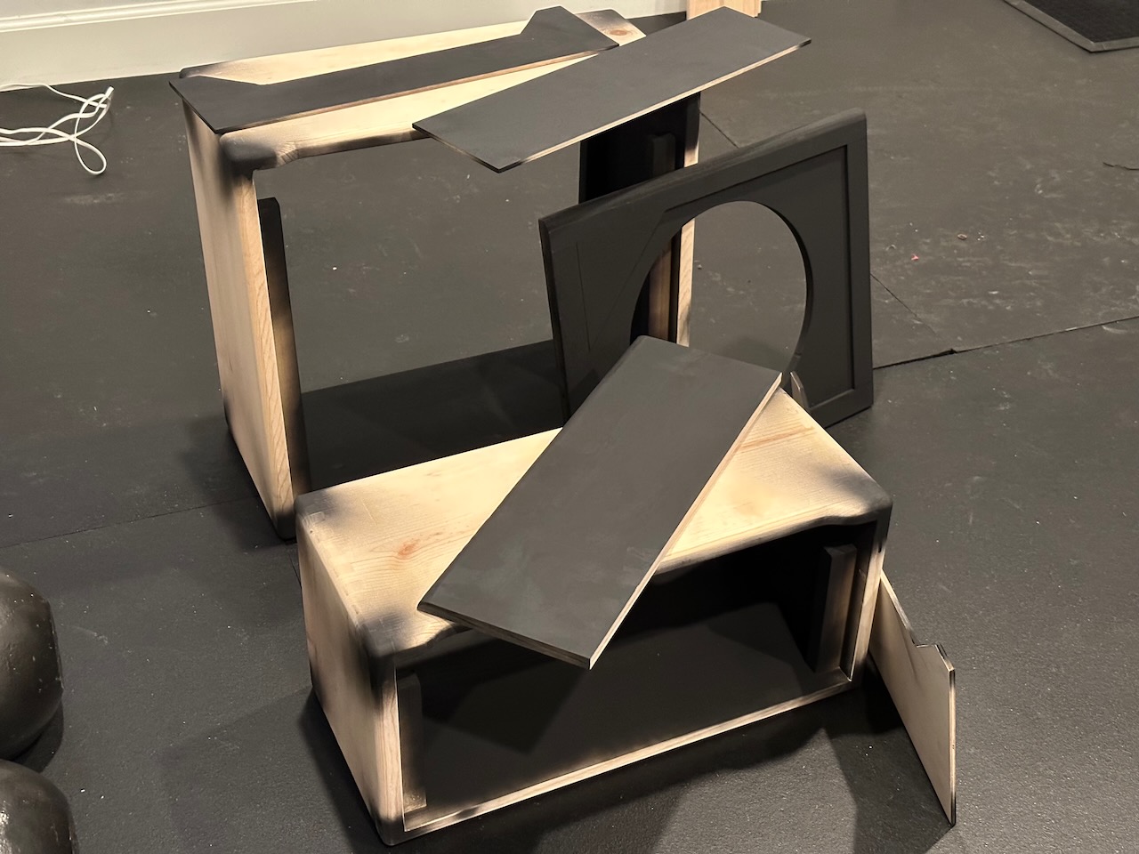
- Reverb tank at a 45° angle inside of an amp head?
- Found source of buzz and hum in AB763 build (a noisy power transformer!)
- Am I measuring the output wattage correctly?
- Help with strange 120Hz hum and horrible squeal in AB763-like build
- Mojotone DR Power Transformer and keeping 6V6 power tubes happy
- Does choke position and orientation matter (headphone test)?
- Rectifier and Output Tube right next to power transformer?
- A/C Mains routing right next to reservoir cap OK?
- Output backup resistor to chassis or circuit ground?
- Capacitors and resistors on RCA Reverb jacks in DR Handwired?
- Orientation of Power Transformer
- Purpose of capacitor in parallel with R2 in elevated heater voltage divider?
- Function of a diode in parallel with the bypass capacitor of the reverb driver stage?
- Grid stoppers on nearly all preamp tubes of ‘64 Custom Deluxe Reverb (Handwired)?
- Phase inverter ground (through NFB tail resistor) to power amp ground in AB763?
- What factors contribute to higher output volume and power?
- Correct way for adding a bias balance pot?
- What series of Nichicon caps to use for filter caps?
- Extremely low output volume in brand new AB763 build?
- AmplifiedParts or Mojotone Tolex Glue?
- Deluxe Reverb Hand-wired with V1B and V3B plates wired together?
- Reverb driver transformer angle
- Discovering some mods in a 65 DRRI 2013 & tremolo question
- Help needed: Let’s track down this 60Hz hum with a scope
Voltage Readings
Wall voltage: 122VAC
Heaters: 6.56VAC
Rectifier Heater: 5.19VAC
PT Main Primaries: 721VAC
B+: 459V
B+2: 457V
B+3: 397V
B+4: 392V
Bias supply: 50.5VAC
Rectified bias: -58.6V
Bias after bias pot: -43.9V
| Pin 1 | Pin 2 | Pin 3 | Pin 4 | Pin 5 | Pin 6 | Pin 7 | Pin 8 | |
|---|---|---|---|---|---|---|---|---|
| V1 7025 Preamp | 260 | 1.963 | 258.8 | 1.974 | ||||
| V2 12AT7 Reverb Driver | 452 | 14mV | 8.6 | 452 | 14mV | 8.6 | ||
| V3 7025 Reverb Recovery | 259.7 | 2.176 | 257.1 | 2.176 | ||||
| V4 7025 Tremolo | 189.2 | 1.633 | 457 | 189.1 | 193.2 | |||
| V5 12AT7 Phase Inverter | 241.6 | 50.7 | 83.2 | 240 | 52.6 | 83.2 | ||
| V6 6V6 Power Tube | -43.9 | 459 | 457 | -43.9 | 457 | 19.7mV | ||
| V7 6V6 Power Tube | -43.8 | 459 | 457 | -43.9 | 457 | 19.9mV | ||
| V8 GZ34 Rectifier | 459 |
Schematic and Wiring Diagram
WARNING Amplifiers have large capacitors that store enough electricity to kill even when the amplifier is unplugged. If you open an amplifier you MUST verify no voltage remains in the capacitors before working inside it. See more amp safety info here from robrobinette.com.
I’m providing the schematic and layout diagrams here in hopes that it may help someone down the road. If it helps you, I’d love to hear your experience with your build. Feel free to contact me at boyd at boydtimothy dot com.
Download the schematic here. (diylc - right-click and select “Save as…”)
Download the layout diagram here. (diylc - right-click and select “Save as…”)